
Lamp

A technology for lamps and lamp caps, which is applied to lighting devices, electric light sources, and components of lighting devices, etc., can solve the problems of unstable fixing effect, disconnection between lamp cap and lamp housing wires and conductive joints, and unusable lamps and lanterns. It is not easy to achieve Disconnection, improve fixing effect, good heat dissipation effect

Inactive Publication Date: 2017-05-10
周晓东
View PDF0 Cites 0 Cited by
  • Summary
  • Abstract
  • Description
  • Claims
  • Application Information

AI Technical Summary

Problems solved by technology

Although this structure is simple, the fixing effect between the lamp cap and the lamp shell and between the wire and the conductive joint is not stable enough, which may easily cause the disconnection between the lamp cap and the lamp shell, as well as the wire and the conductive joint, so that the lamp cannot be used.

Method used


Image

  • Lamp
  • Lamp

Examples


Embodiment Construction

[0011] The present invention will be further described below in conjunction with the accompanying drawings and embodiments.

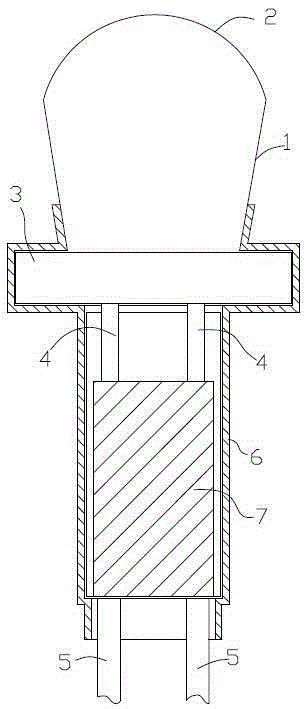
[0012] Such as figure 1 As shown, a lamp provided by the present invention includes a lamp cap, and the lamp cap includes an aluminum reflector 1, and a luminous body is arranged in the reflector, and the radius of the reflector gradually increases from bottom to top. Such setting can improve the heat dissipation effect of the lamp , the upper end of the reflective cup is provided with an optical lens 2, and the lower end of the reflective cup is provided with a lamp holder 3. The radius of the lamp holder is larger than the radius of the lower end of the reflective cup. 4 passes through the lamp holder 3 and is exposed outside the lamp holder, the conductive joint 4 is welded to the wire 5, the lower end of the reflector cup, the lamp holder and the wire are evenly positioned in the lamp housing 6, and the fixing of the lamp holder and the lamp housing...


PUM


Abstract

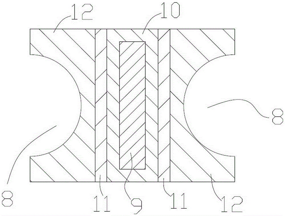
The invention discloses a lamp. The lamp comprises a lamp cap, wherein a luminous body is arranged in the lamp cap; two conductive joints are arranged at the lower end of the lamp cap; each conductive joint is welded with a conductive wire; the lower end of the lamp cap and the conductive wires are located in a lamp shell; the lamp cap comprises a light-reflecting cup; the radius of the light-reflecting cup is gradually increased from bottom to top; an optical lens is arranged at the upper end of the light-reflecting cup; a lamp holder is arranged at the lower end of the light-reflecting cup; the radius of the lamp holder is greater than the radius of the lower end of the light-reflecting cup; each conductive joint penetrates through the lamp holder and is welded with the corresponding conductive wire in the lamp shell; the lower end of the light-reflecting cup and the lamp holder are located in the lamp shell; a fixing sleeve is further arranged in the lamp shell; grooves are formed in the two sides of the fixing sleeve; and the weld of each conductive wire and the corresponding conductive joint is located in the corresponding groove. Through improvement for the abovementioned structure, the fixing effect between the lamp cap and the lamp shell and between each conductive wire and the corresponding conductive joint is greatly improved, a disjointing phenomenon is not easily caused, and a good heat dissipation effect is achieved.

Description

technical field [0001] The invention relates to a lamp. Background technique [0002] The lamps currently in use include a lamp cap. A luminous body is arranged in the lamp cap. The lower end of the lamp cap is provided with two conductive joints electrically connected to the luminous body. The conductive joints are welded to the wires. Although this structure is simple, the fixing effect between the lamp cap and the lamp housing and between the wire and the conductive joint is not stable enough, which may easily cause the disconnection between the lamp cap and the lamp housing and the wire and the conductive joint, thereby making the lamp unusable. Contents of the invention [0003] In order to solve the shortcomings of the above-mentioned prior art, the object of the present invention is to provide a lamp. [0004] In order to achieve the above object, a lamp designed by the present invention includes a lamp base, a luminous body is arranged inside the lamp base, and tw...

Claims


Application Information

Patent Timeline
IPC IPC(8): F21S2/00F21V23/06F21V17/10F21V7/22
CPCF21S2/00F21V23/06
Inventor 周晓东
Owner 周晓东
Learn More