Pre-separation effect test method for oil-gas separator

A technology of oil and gas separator and test method, which is applied in the directions of machines/engines, pumping devices for elastic fluids, rotary piston type/oscillating piston type pump components, etc., and can solve the problem of large oil removal pressure of filters, Shorten service life, increase maintenance cost and other problems, achieve the effect of reducing degreasing pressure, reducing maintenance cost and improving quality level

Active Publication Date: 2017-05-10
NANJING CRRC PUZHEN HAITAI BRAKE EQUIP CO LTD
View PDF7 Cites 1 Cited by
  • Summary
  • Abstract
  • Description
  • Claims
  • Application Information

AI Technical Summary

Problems solved by technology

Since the compressor under test usually uses a new oil filter element, the test results of the compressed air quality level are often covered up by the new filter element, which cannot fundamentally reflect the oil removal ability of the compressor itself. The ability is poor, which often causes a large oil removal pressure on the oil separation core and the back-end filter, which greatly shortens its service life and increases maintenance costs.

Method used


Image

  • Pre-separation effect test method for oil-gas separator
  • Pre-separation effect test method for oil-gas separator
  • Pre-separation effect test method for oil-gas separator

Examples


Embodiment Construction

[0023] In order to make the purpose, technical solutions and advantages of the embodiments of the present invention more clear, the technical solutions in the embodiments of the present invention will be clearly and completely described below in conjunction with the drawings in the embodiments of the present invention.

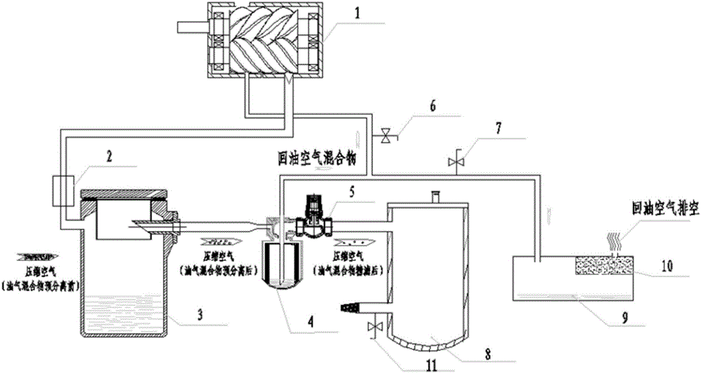
[0024] like figure 1 As shown, the hardware used in the pre-separation effect test method of the oil-gas separator includes: screw compressor 1, oil-gas separator 3, oil separation core 4, pressure stabilizing air cylinder 8, oil collection box 9, and the compressed air output port of screw compressor 1 The flow rate adjustment device 2 is connected to the inlet of the oil-gas separator 3, the compressed air outlet of the oil-gas separator 3 is connected to the pressure-stabilizing air cylinder 8 through the oil separation core 4 and the minimum pressure valve 5, and the bottom of the oil-gas separator passes through the primary oil return pipeline (not shown i...


PUM


Abstract

The invention relates to a pre-separation effect test method for an oil-gas separator. By the method, pre-separation effects of the oil-gas separator can be simply and effectively tested, the matching relation between an oil-gas separator separation structure with optimal separation effects and inlet velocity is sought by testing, the oil removing pressure of an after-treatment system is reduced, the replacement period of damageable and consumable parts of the after-treatment system can be effectively prolonged, maintenance cost is reduced, and compressed air quality grade is improved.

Description

technical field [0001] The invention relates to a pre-separation effect test method of a screw air compressor oil-gas separator for rail transit, and belongs to the technical field of rail transit vehicle brake systems. Background technique [0002] With the development of product technology in the rail transit industry, in the field of braking systems, owners are increasingly aware of the importance of compressed air quality levels, maintenance costs, and environmental protection. For this reason, owners put forward higher and higher requirements on the air quality level of rail transit compressors and the replacement cycle of related vulnerable and consumable parts. [0003] In the existing test methods, the measurement of the oil content in the compressed air of the screw compressor is usually to test the compressed air at the final outlet of the post-treatment system. Since the compressor under test usually uses a new oil filter element, the test results of the compress...

Claims


Application Information

Patent Timeline
Patent Type & Authority Applications(China)
IPC IPC(8): F04C29/02
CPCF04C29/026
Inventor 郭志刚牛瑞章萍李逵
Owner NANJING CRRC PUZHEN HAITAI BRAKE EQUIP CO LTD
Why Eureka
Try Eureka