Eureka AIR delivers breakthrough ideas for toughest innovation challenges, trusted by R&D personnel around the world.

Underwater cleaner

A technology of cleaners and passages, applied in ship cleaning devices, ship construction, ships, etc., can solve the problems of vortex, high fluid loss, invisible filling degree, etc., and achieve the effect of high flow rate and high suction power

Active Publication Date: 2017-05-10
安德烈斯弗兰克尔
View PDF9 Cites 3 Cited by
  • Summary
  • Abstract
  • Description
  • Claims
  • Application Information

AI Technical Summary

Problems solved by technology

An inner dirt collection chamber is formed between the first channel section and the second channel section, wherein the fluid cross-section is in the region of the opening of the first channel section into the dirt collection chamber and from the dirt collection chamber A sudden change in the exit region into the second channel section, which leads to eddies and relatively high fluid losses
Another disadvantage of the internal dirt collection chamber is that the filling level is not visible from the outside and the housing needs to be opened in order to empty the dirt collection chamber

Method used


Image

  • Underwater cleaner
  • Underwater cleaner
  • Underwater cleaner

Examples


Embodiment Construction

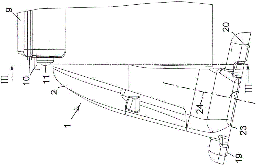
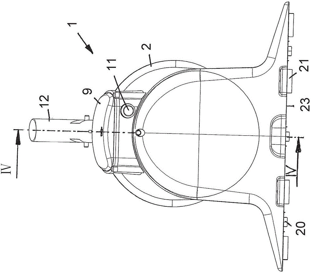
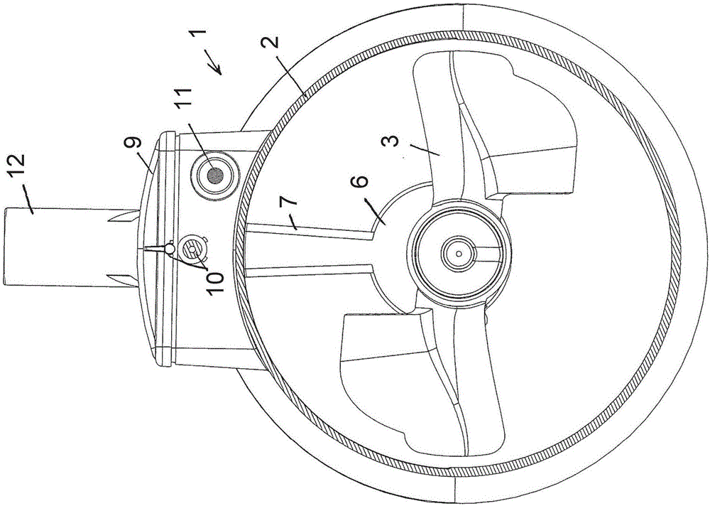
[0026] The underwater cleaner 1 for swimming pools shown in the figures comprises, for example, a housing 2 in which an impeller 3 with an electric motor 4 and a gear 5 operates as a pump. The impeller 3 is driven by a motor 4 via a gear 5 . The motor 4 and the gear 5 as well as the mountings for the impeller 3 are housed in the pump housing 6 . The pump housing 6 is connected to the housing 2 via a suspension 7 . A rechargeable battery 8 is arranged, for example, above the suspension 7 , on the upper side of the housing 2 . The battery 8 is arranged in a waterproof manner, sealed within the housing 2 by a battery housing cover 9 . A closure 10 for the battery housing cover 9 is attached to the housing 2 . In order to house the electrical connection between the electric motor 4 and the battery 8 inside said suspension, the suspension 7 is hollow. Located on the outside of the housing 2 and adjacent to the closure 10 is a switch 11 via which the power supply to the motor 4 ...


PUM


Abstract

The invention relates to an underwater cleaner, in particular for a swimming pool, comprising a housing in which is arranged an especially battery - operated pump with an electric motor and an impeller and a second channel section, which accommodates the impeller, the second channel section having a first channel section, the first channel section is arranged inclined relative to the first channel section, and the impeller axis is arranged inclined to a normal on the opening cross section of the inlet opening. The ratio A / B of a first cross-sectional area A to a second cross-sectional area B is less than 2.8, the first cross-sectional area A being defined by the smallest cross-section of flow in the first channel section 13 and the second cross-sectional area B by the smallest cross-section of the second channel section is defined directly at the pump inlet. In order to obtain a very simple and productive underwater cleaner and to realize high suction effects with relatively little flow losses in the case of wheels with relatively large diameters, the first channel section transits into the second channel section.

Description

technical field [0001] The invention relates to an underwater cleaner, in particular for swimming pools, comprising a housing in which is arranged an in particular battery-driven pump with an electric motor and an impeller, wherein the housing comprises a an inlet opening and an outlet opening, the fluid path forming a first channel section starting from the first inlet opening and a second channel section accommodating the impeller, wherein the second channel section is inclined relative to the first channel section and the axis of the impeller is arranged in an oblique manner relative to the normal of the opening section of the inlet opening, and wherein the ratio A / B of the first cross-sectional surface A to the second cross-sectional surface B is less than 2.8, wherein the first A cross-sectional surface A is defined by the smallest flow section in the first channel section and a second cross-sectional surface B is defined by the smallest fluid section in the second channe...

Claims


Application Information

Patent Timeline
Patent Type & Authority Applications(China)
IPC IPC(8): E04H4/16
CPCE04H4/1654E04H4/1636E04H4/1618B63B59/08B63B2059/082
Inventor 安德烈斯·弗兰克尔
Owner 安德烈斯弗兰克尔
Why Eureka
Eureka Blog
Learn More