Cooking device

A technology of cooking equipment and pots, which is applied in the field of cooking equipment, can solve the problems of poor consistency of mechanism motion performance, high equipment energy consumption, large vibration and noise, etc., and achieve the goals of reducing cooking energy consumption, large heating area, and reduced volume Effect

Active Publication Date: 2017-05-10
AIC ROBOTICS TECH
View PDF16 Cites 5 Cited by
  • Summary
  • Abstract
  • Description
  • Claims
  • Application Information

AI Technical Summary

Problems solved by technology

[0005] The disadvantages of the above prior art solutions are: (1) poor consistency of mechanism motion performance, completely relying on the motion of the pot to realize turning over the pot, requiring extremely high control accuracy of the motion of the pot, and damping of the mechanism (such as after assembly and long-term operation) The damping caused by wear, oil stains, etc.) is also very sensitive to changes, and when the amount of cooking materials changes, it is usually necessary to adjust the motion parameters of the pot, otherwise it is easy to cause materials to fall out of the pot or The problem that the material cannot be turned over effectively; (2) Since the pot usually has a large weight, the way of turning the pot through the movement of the pot has high energy consumption and easy damage to the equipment, and the vibration and vibration during the turning process Defects such as loud noise

Method used


Image

  • Cooking device
  • Cooking device
  • Cooking device

Examples


Embodiment 1

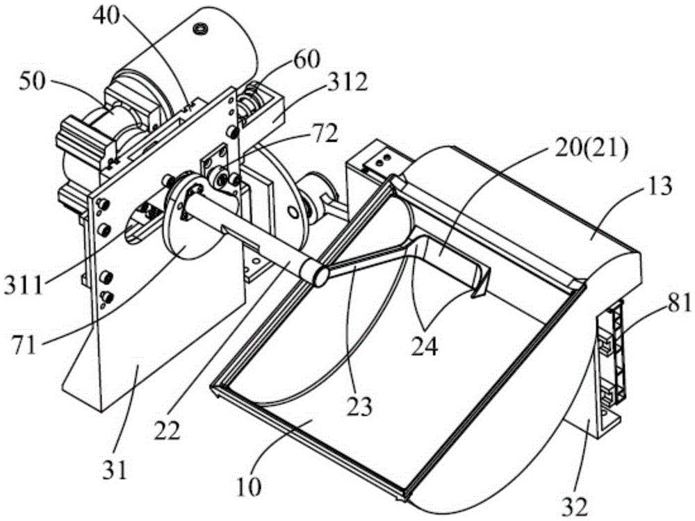
[0039] figure 1 and 2 It is a structural schematic diagram of Embodiment 1 of the cooking equipment of the present invention. Such as figure 1 As shown, the cooking equipment of this embodiment includes a frame 31, a pot 10, a stir-frying component 20 and a stir-frying motor 50 as a stir-frying power device. Wherein, the frame 31 is provided with a slider member 40, the stir-fry member 20 and the stir-fry motor 50 are arranged on the slider member 40; the rotating shaft 22 of the stir-fry member 20 passes through the strip hole 311 on the frame 31, and It is connected with the output shaft of the frying motor 50 through a coupling (not visible in the figure).

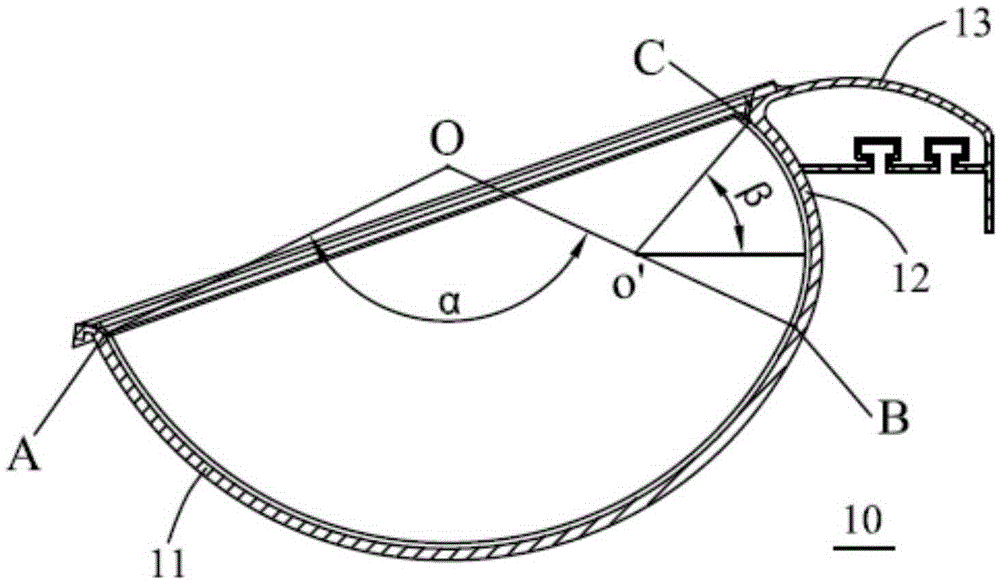
[0040] The pot 10 extends along its longitudinal direction and is roughly formed in a groove shape, and the inner contours of each cross section thereof are substantially the same. The stir-frying member 20 includes a working end 21 adapted to the inner wall of the pot 10, a connecting arm 23 connecting the working ...

Embodiment 2

[0049] Figure 7 and 8 It is a structural schematic diagram of Embodiment 2 of the cooking equipment of the present invention. Such as Figure 7 and 8 As shown, the cooking apparatus includes a pan 110 and a pan support 131 . Wherein, the pot support 131 has a guide rail 1311 and a guide rail 1312, the guide rail 1311 is provided with a slider member 111, the guide rail 1312 is provided with a slider member 181, and the side of the cooker 110 provided with the turning part is detachably supported on the slider. The opposite side of the block member 181 is rotatably connected to the slider member 111 . In this embodiment, the pot 110 also includes a pot body and a turning part. Since the structure of this part of the pot 110 is the same as that in Embodiment 1, a detailed description thereof is omitted here.

[0050] The cooking equipment also includes a pot shaking motor 190, a connecting rod member 182, and a crank member 183 connected with the pot shaking motor 190 and ...


PUM


Abstract

The invention provides a cooking device, which comprises a cooker, comprising a pot body and a back turning part extending from the cooker body; a frying mechanism, comprising a stir fry power device and a stir frying component. Wherein, the working end of the stir frying component is matched with the inner wall of the cooker body, and the inner part of the cooker is moved from the main body of the cooker to the turning part along with the inner wall of the cooker. The cooking device realizes the effect of pan frying through the matching of the frying component and the cooker. There is no need to control the complex movement of the cooker as a simulated cook and manually turn the pan, which can effectively reduce the cooking energy consumption. In addition, because the material in the cooking process acts under the guidance of the turning back part, the inner movement of the pan is carried out, so that the material does not fall outside the pot.

Description

technical field [0001] The present invention relates to a cooking device; more specifically, the present invention relates to a cooking device for cooking. Background technique [0002] Turning the pot is one of the most commonly used and basic cooking actions in Chinese cooking. A good turning effect can make the ingredients heated evenly and have the same maturity, thus ensuring the quality of the dishes. In traditional Chinese cooking, pot turning is usually performed by the chef in a periodical motion of "lifting and lifting" the pot to control the rapid deceleration / acceleration of the pot during the movement, so that the cooked materials in the pot This is achieved by tossing it along the edge of the pan, flipping it over and then dropping it into the pan. According to the need to control the strength of turning the pot, large turning and small turning can be realized respectively. During big turning, most or all of the materials in the pot are turned over at one time...

Claims


Application Information

Patent Timeline
IPC IPC(8): A47J27/00A47J36/00
CPCA47J27/00A47J36/00
Inventor 严平
Owner AIC ROBOTICS TECH
Why Eureka
Try Eureka