
Method and device for predicting collision between objects

A prediction method and technology of a prediction device, which are applied in the field of collision prediction between objects, can solve the problems of difficulty in clearly defining the rear boundary of the preceding vehicle, inaccurate determination of collision time, and inability to intuitively express the risk of collision, etc. Small, low cost, easy to achieve

Inactive Publication Date: 2017-04-19
上海为森车载传感技术有限公司
View PDF10 Cites 7 Cited by
  • Summary
  • Abstract
  • Description
  • Claims
  • Application Information

AI Technical Summary

Problems solved by technology

Although judging according to the width of the vehicle can overcome the problem of limited installation position of the camera, in the actual driving process, the current vehicle is often not directly in front of the vehicle. Therefore, the camera can not only collect the image of the rear of the vehicle in front, but also The image of the side of the vehicle in front is collected, which makes it difficult for the system to clearly define the boundary of the rear of the vehicle in front, and cannot determine the actual width of the rear of the vehicle in front, resulting in inaccurate determination of the collision time
[0007] Prior art 4: The scheme disclosed in the invention with the authorized announcement number CN100386595C and the title "A vehicle collision avoidance warning method and its device" can only obtain the distance between the same feature points in two or more images. However, the speed of change of the distance between feature points cannot intuitively express the risk of collision during driving, so the solution of prior art 4 cannot predict the risk of collision, and needs to be supplemented by other calculation rules or model to achieve this
[0008] For the above problems, no effective solutions have been proposed so far

Method used


Image

  • Method and device for predicting collision between objects
  • Method and device for predicting collision between objects
  • Method and device for predicting collision between objects

Examples


Embodiment Construction

[0065] The description of this illustrative embodiment should be taken in conjunction with the accompanying drawings, which should be considered a part of this complete specification. In the drawings, the shapes or thicknesses of the embodiments may be exaggerated and marked for simplification or convenience. Furthermore, parts of each structure in the drawings will be described separately. It should be noted that elements not shown in the drawings or described in words are forms known to those of ordinary skill in the art.

[0066] The descriptions of the embodiments here, any references to directions and orientations are just for convenience of description, and should not be construed as any limitation to the protection scope of the present invention. The following descriptions of the preferred embodiments involve combinations of features, which may exist independently or in combination, and the present invention is not particularly limited to the preferred embodiments. The...


PUM


Abstract

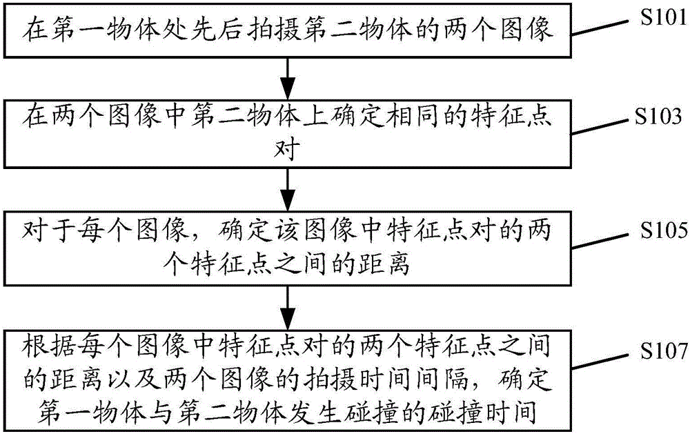
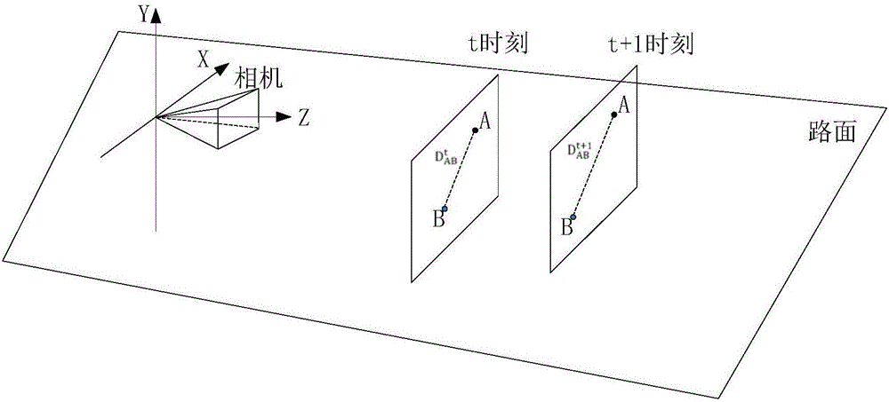
The invention discloses a method and a device for predicting the collision between objects. The method comprises the following steps: shooting two images of a second object at the position of a first object; determining an identical feature point pair on the second object in the two images; determining the distance between the two feature points of the feature point pair in each image; and determining the time of collision between the first object and the second object according to the distance between the two feature points of the feature point pair in each image and the shooting time interval of the two images. The predicted collision time can visually represent the collision risk at the current moment, and thus, drivers can be warned in a timely manner to perform a corresponding operation. Moreover, the method and the device have the advantages of high accuracy, good reliability, convenient use, low cost, low power consumption, and the like.

Description

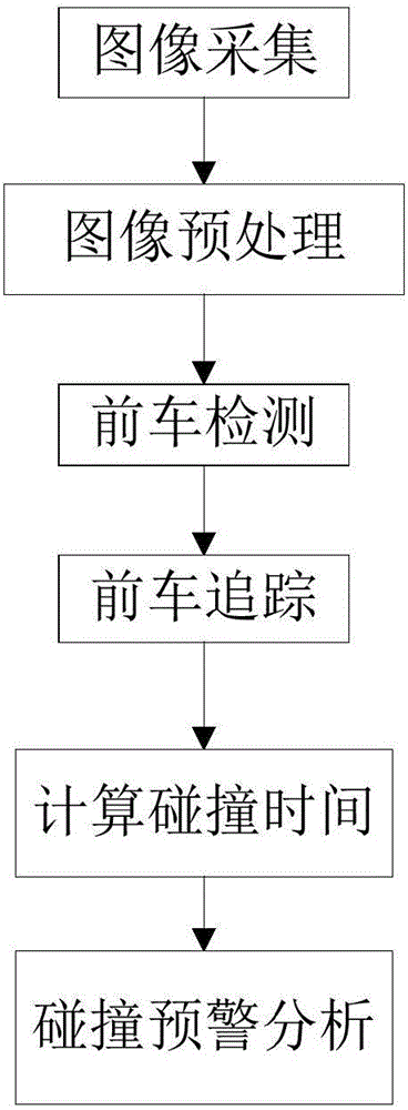
technical field [0001] The invention relates to a collision prediction method and device between objects. Background technique [0002] With the rapid development of the automobile industry, the number of vehicles on the road has increased significantly, and automobile collision accidents have occurred frequently. Improper operation of the driver himself is one of the main causes of accidents. If it is possible to predict the occurrence of collision accidents and give appropriate warnings to drivers, it is of great significance for reducing traffic accidents and improving driving safety. In recent years, an image-based advanced driver assistance system (Advanced Driver Assistant System, referred to as ADAS) has received extensive attention. ADAS usually has a collision warning system, which collects video streams by means of a camera installed on the vehicle, and then estimates the possible collision time between the vehicle and the vehicle in front, thereby predicting pot...

Claims


Application Information

Patent Timeline
IPC IPC(8): G06K9/00B60W30/095
CPCB60W30/0956G06V20/584G06V2201/08B60W2420/403
Inventor 王艳明刘国伟
Owner 上海为森车载传感技术有限公司
Learn More