Potential energy recovery utilization system, control method and engineering machinery equipment

A potential energy recovery and control method technology, applied in mechanical equipment, engines, electromechanical devices, etc., can solve the problems of complex system structure, increase cost, increase system complexity and cost, etc., achieve simple system structure, realize continuous recovery and recycling. The effect of using

Active Publication Date: 2017-04-12
JIANGSU XCMG CONSTR MASCH RES INST LTD
View PDF7 Cites 5 Cited by
  • Summary
  • Abstract
  • Description
  • Claims
  • Application Information

AI Technical Summary

Benefits of technology

In this technology for recycling or regenerating energy from an elevator machine it uses two types of motors - one works with constant speed while another tries to match its own speeds by adjusting certain parameters like voltage levels during operation. By controlling these variables, the machines are able to convert their kinetic energy back into electricity efficiently without adding extra parts.

Problems solved by technology

This technical problem addressed in this patents relates to improving the efficiency and effectiveness of construction machines that use hoist-lifting mechanisms like lifting platforms (also called scaffolders) used at building sites. These machine tools have heavy loads due to their own gravity while being lifted up from high points on buildings where they may fall over accidentally causing damage. To address these issues, various methods were developed including regenerative braking systems and hydrostatic power recovery systems. However, existing solutions involve adding extra components to achieve better performance compared to traditional ways.

Method used


Image

  • Potential energy recovery utilization system, control method and engineering machinery equipment
  • Potential energy recovery utilization system, control method and engineering machinery equipment
  • Potential energy recovery utilization system, control method and engineering machinery equipment

Examples


Embodiment Construction

[0030] The present invention will be described in detail below. In the following paragraphs, different aspects of the embodiments are defined in more detail. Aspects so defined may be combined with any other aspect or aspects unless specifically stated otherwise. In particular, any feature considered to be preferred or advantageous may be combined with one or more other features which are considered to be preferred or advantageous.

[0031] Terms such as "first" and "second" appearing in the present invention are only for convenience of description, to distinguish different components with the same name, and do not indicate a sequence or a primary and secondary relationship.

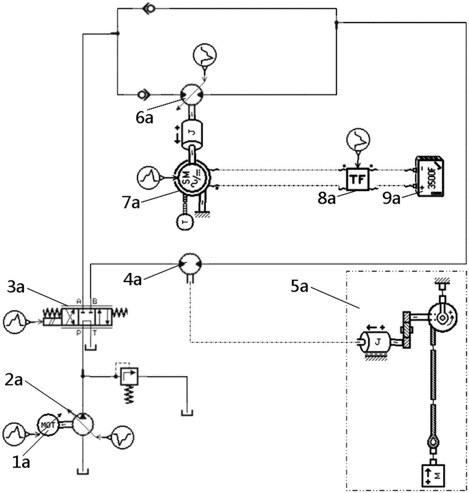
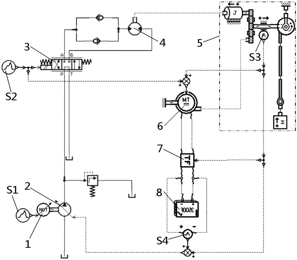
[0032] Such as figure 2 As shown, in order to recycle the potential energy of the hoisting system 5 in construction machinery equipment, the present invention provides an improved potential energy recovery and utilization system. In order to facilitate the subsequent description and understanding of t...


PUM


Abstract

The invention relates to a potential energy recovery utilization system, a control method and engineering machinery equipment; the potential energy recovery utilization system comprises a DC motor (6), an electric energy storage part (8) and a control part; the DC motor (6) comprises an input end and an output end, wherein the input end is connected with a rotary part in a winch system (5), and the output end is connected with the electric energy storage part (8); the control part is used for controlling the DC motor (6) to work in a corresponding mode according to different working conditions, thus realizing energy conversion. The potential energy recovery utilization system can use the DC motor to simultaneously realize the winch system lowering potential energy recovery and utilization, can directly convert the mechanical energy into electric energy in energy recovery, can release stored energy without adding new parts, so the system structure can be simpler, thus using low cost to realize energy recovery utilization.

Description


Claims


Application Information

Patent Timeline
Owner JIANGSU XCMG CONSTR MASCH RES INST LTD
Why Eureka
Try Eureka