Fully-automatic shaping mechanism for welding joint of pressure water storage bucket

A water storage bucket, fully automatic technology, applied in turning equipment, turning equipment, metal processing and other directions, can solve the problems of low production efficiency, high labor intensity and high labor cost

Active Publication Date: 2017-04-05
ZHEJIANG GUANGYUE ENVIRONMENTAL POLYTRON TECH INC
View PDF6 Cites 1 Cited by
  • Summary
  • Abstract
  • Description
  • Claims
  • Application Information

AI Technical Summary

Problems solved by technology

[0002] The structure of the pressure water storage barrel is usually divided into upper barrel body, lower barrel body and inner tank. During manufacturing, the upper and lower barrel bodies are manufactured separately and then connected into one body by welding, while the middle weld needs to be carried out. Edge trimming and shaping processing, the existing shaping mechanism includes a frame, a turntable and a bracket are set on the frame, a compression sleeve is set on the bracket, the compression sleeve is driven by a compression cylinder, and the edge trimming is set on the side of the turntable on the frame. Device, during processing, the worker turns the welded pressure water storage bucket to the specified direction and puts it on the turntable, and then the compression cylinder drives the compression sleeve to press and position the pressure storage bucket, and the motor drives the turntable to rotate, and the turntable drives the pressure The water storage barrel and the compression sleeve rotate together. At this time, the turning tool of the trimming device enters the weld seam on the surface of the pressure water storage barrel for trimming and shaping. After the processing is completed, the worker takes out the pressure water storage barrel and takes it to the next process. Among them, the disadvantages of this structure are: loading and unloading must be manually operated, the production efficiency is low, the labor intensity of the workers is high, and the labor cost is high

Method used


Image

  • Fully-automatic shaping mechanism for welding joint of pressure water storage bucket
  • Fully-automatic shaping mechanism for welding joint of pressure water storage bucket
  • Fully-automatic shaping mechanism for welding joint of pressure water storage bucket

Examples


Embodiment Construction

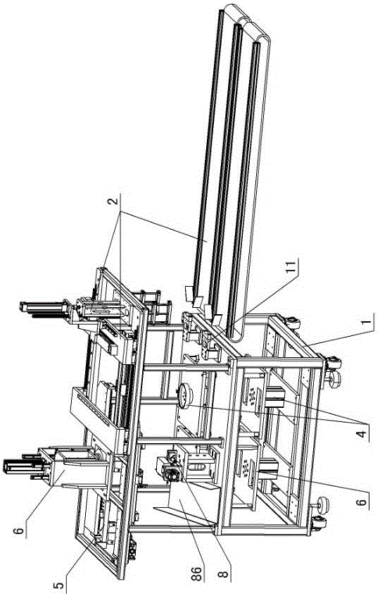
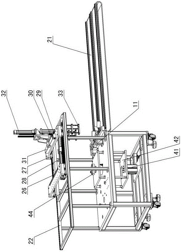
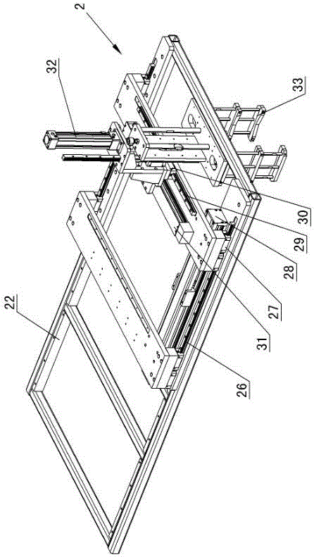
[0020] The invention relates to a fully automatic seam shaping mechanism for a pressure water storage tank, such as figure 1 — Figure 8Shown, comprise frame 1, be provided with feeding device 2, positioning device 4, feeding device 5, trimming rotating device 6 and trimming shaping device 8 on the frame; Described feeding device 2 comprises feeding conveyor belt 21 And support 22, the pressure water storage tank 23 is set on the feeding conveyor belt, the air filling nozzle 24 is set under the pressure water storage tank, the support is fixed with the frame 1, the X-direction slide rail 26 is arranged on the support, and the X-direction slide rail is provided on the X-direction slide rail. Slider 27, the X-direction slider is driven by the X-direction moving cylinder 28, the Y-direction slide rail 29 is set on the X-direction slide rail, the Y-direction slide block 30 is arranged on the Y-direction slide rail, and the Y-direction slider moves through the Y-direction cylinder ...


PUM


Abstract

The invention discloses a fully-automatic shaping mechanism for a welding joint of a pressure water storage bucket. The fully-automatic shaping mechanism comprises a rack, wherein a loading device, a location device, a feeding device, a trimming rotation device and a trimming shaping device are arranged on the rack. According to the fully-automatic shaping mechanism for the welding joint of the pressure water storage bucket and adopting the scheme, loading, rotary location, feeding, compression rotation and trimming shaping are automatically carried out on the pressure water storage bucket subjected to welding through arranging the loading device, the location device, the feeding device, the trimming rotation device and the trimming shaping device on the rack, the action is fully-automatic, manual operation is not required, the labour intensity of workers is reduced, the manual cost is reduced, and the production efficiency is increased.

Description

technical field [0001] The invention relates to a processing device for a pressure water storage barrel, in particular to a fully automatic welding seam shaping mechanism for a pressure water storage barrel. Background technique [0002] The structure of the pressure water storage barrel is usually divided into upper barrel body, lower barrel body and inner tank. During manufacturing, the upper and lower barrel bodies are manufactured separately and then connected into one body by welding, while the middle weld needs to be carried out. Edge trimming and shaping processing, the existing shaping mechanism includes a frame, a turntable and a bracket are set on the frame, a compression sleeve is set on the bracket, the compression sleeve is driven by a compression cylinder, and the edge trimming is set on the side of the turntable on the frame. Device, during processing, the worker turns the welded pressure water storage bucket to the designated direction and puts it on the turn...

Claims


Application Information

Patent Timeline
Patent Type & Authority Applications(China)
IPC IPC(8): B23B5/00B23Q7/04B23Q7/00
CPCB23B5/00B23Q7/00B23Q7/04
Inventor 楼云光
Owner ZHEJIANG GUANGYUE ENVIRONMENTAL POLYTRON TECH INC
Why Eureka
Try Eureka