Material taking platform of conductive foam of antenna body
A technology of conductive foam and the main body of the antenna, applied in the direction of the antenna, antenna parts, circuits, etc., can solve the problems of unstable production efficiency and production capacity, rework and repeated operations, material scrapping, etc., to achieve easy transformation and maintenance, and improve product quality. , the effect of simple structure
- Summary
- Abstract
- Description
- Claims
- Application Information
AI Technical Summary
Problems solved by technology
Method used
Image

Examples
Embodiment 1
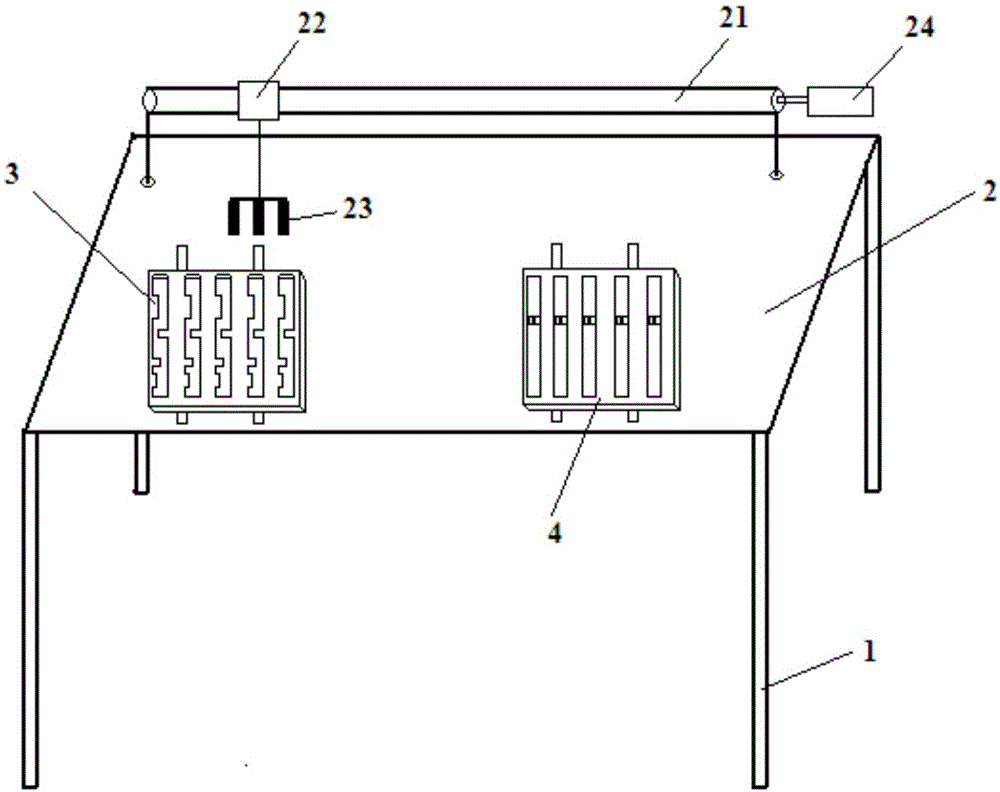
[0019] Such as figure 1 As shown, a retrieving platform for the conductive foam of the antenna main body is used to fetch and send the conductive foam to the antenna main body. 2, the conductive foam carrier 3, the retrieving device and the antenna main body carrier 4, the reclaimer is respectively arranged corresponding to the conductive foam carrier 3 and the antenna main body carrier 4, and the conductive foam carrier 3 is arranged side by side A plurality of conductive foam loading slots, conductive foam is provided in the conductive foam loading slots, and positioning claws are provided on the antenna main body platform 4 .
[0020] The retrieving device includes a motor 24 connected in sequence, a guide rod 21 fixed on the top of the table 2, a slider 22 and a retrieving fork 23, the slider 22 is slidably connected to the guide rod 21, the conductive foam carrier 3 and the antenna main body carrier 4 slide in the direction perpendicular to the guide rod 21 through the g...
Embodiment 2
[0023] A material retrieving platform for the conductive foam of the antenna main body, which is used to deliver the conductive foam to the antenna main body. Conductive foam carrier 3, material retrieving device and antenna main body carrier 4, the material reclaimer is set corresponding to conductive foam carrier 3 and antenna main body carrier 4 respectively, and conductive foam carrier 3 is provided with a plurality of conductive The foam carrier tank is provided with conductive foam cotton in the conductive foam carrier tank, and positioning claws are arranged on the carrier platform 4 of the antenna main body.
[0024] The retrieving device includes a motor 24 connected in sequence, a guide rod 21 fixed on the top of the table 2, a slider 22 and a retrieving fork 23, the slider 22 is slidably connected to the guide rod 21, the conductive foam carrier 3 and the antenna main body carrier 4 slide in the direction perpendicular to the guide rod 21 through the guide rails arr...
Embodiment 3
[0027] A material retrieving platform for the conductive foam of the antenna main body, which is used to deliver the conductive foam to the antenna main body. Conductive foam carrier 3, material retrieving device and antenna main body carrier 4, the material reclaimer is set corresponding to conductive foam carrier 3 and antenna main body carrier 4 respectively, and conductive foam carrier 3 is provided with a plurality of conductive The foam carrier tank is provided with conductive foam cotton in the conductive foam carrier tank, and positioning claws are arranged on the carrier platform 4 of the antenna main body.
[0028] The retrieving device includes a motor 24 connected in sequence, a guide rod 21 fixed on the top of the table 2, a slider 22 and a retrieving fork 23, the slider 22 is slidably connected to the guide rod 21, the conductive foam carrier 3 and the antenna main body carrier 4 slide in the direction perpendicular to the guide rod 21 through the guide rails arr...
PUM
| Property | Measurement | Unit |
|---|---|---|
| Length | aaaaa | aaaaa |
Abstract
Description
Claims
Application Information
 - R&D
- Intellectual Property
- Life Sciences
- Materials
- Tech Scout
- Unparalleled Data Quality
- Higher Quality Content
- 60% Fewer Hallucinations
Browse by: Latest US Patents, China's latest patents, Technical Efficacy Thesaurus, Application Domain, Technology Topic, Popular Technical Reports.
© 2025 PatSnap. All rights reserved.Legal|Privacy policy|Modern Slavery Act Transparency Statement|Sitemap|About US| Contact US: help@patsnap.com