Eureka AIR delivers breakthrough ideas for toughest innovation challenges, trusted by R&D personnel around the world.

A negative pressure ignition separation device

A separation device and negative pressure technology, applied in the field of solid fuel stoves, can solve the problems of poor fuel combustion, affecting heat exchange, flue gas discharge, and dust adhesion, etc., to reduce the generation of harmful substances, improve combustion efficiency, The effect of eliminating leakage hazards

Active Publication Date: 2018-09-28
青岛博一伟道电子技术有限公司
View PDF6 Cites 0 Cited by
  • Summary
  • Abstract
  • Description
  • Claims
  • Application Information

AI Technical Summary

Problems solved by technology

Once the fire is half-extinguished, because the furnace contains low-carbon coal and dark fire that is not fully burned, the fuel is difficult to burn completely, and it is also easy to cause harmful substances such as smoke particles, carbon monoxide and sulfur monoxide to be discharged with the flue gas
And it is difficult to ignite again, and it needs to consume igniters such as firewood and paper, accompanied by a large amount of smoke and dust
It not only has complicated procedures and high cost, but also has slow ignition speed, poor fuel combustion effect and high pollution
In the conventional coal combustion process, due to the gradual cooling of the high-temperature flue gas in the exhaust, a large amount of tar is formed to adhere to the inner wall of the pipe, and further promotes the adhesion of smoke and dust, which ultimately affects heat transfer and flue gas discharge

Method used


Image

  • A negative pressure ignition separation device
  • A negative pressure ignition separation device
  • A negative pressure ignition separation device

Examples


Embodiment 1

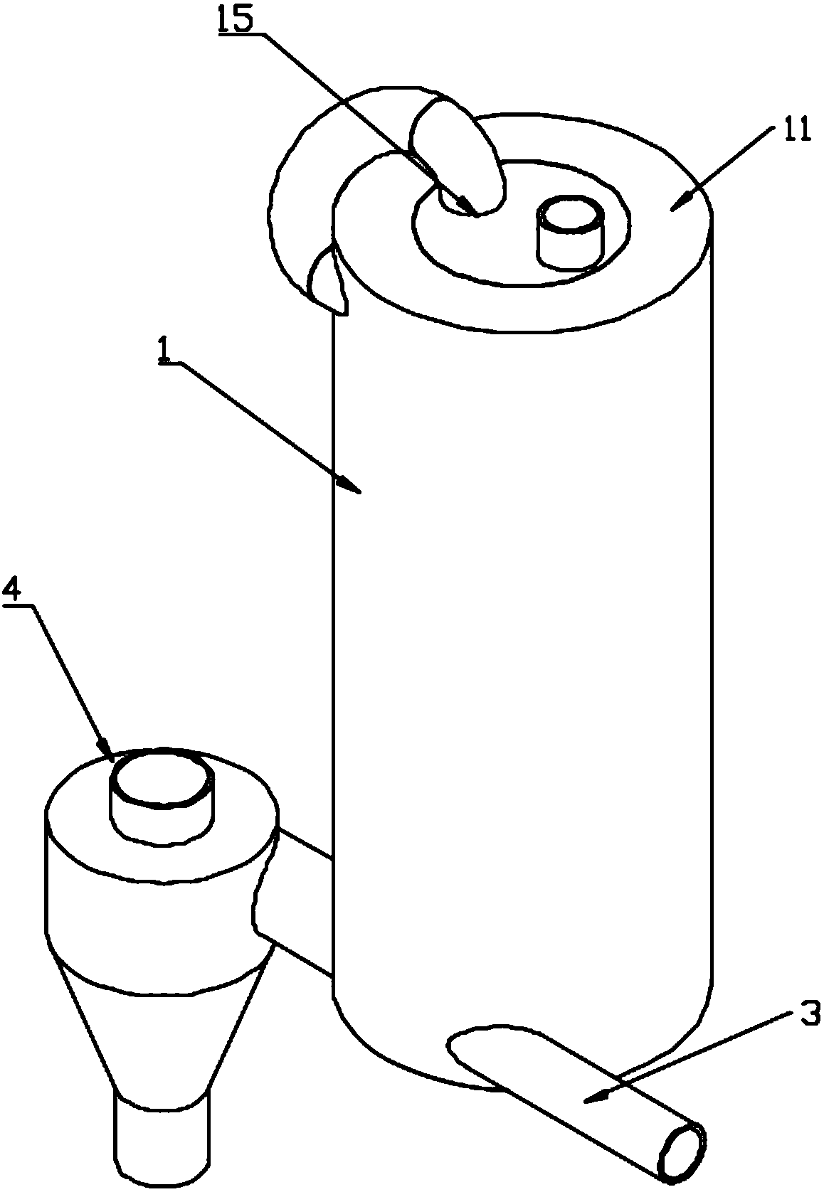
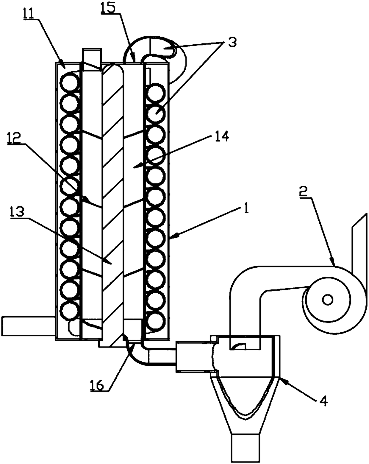
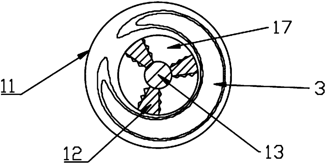
[0032] A negative pressure ignition separation device includes a furnace body 1 and a fan 2, the furnace body 1 includes a furnace wall 11, a baffle plate 12 and an ignition pipe 13; the furnace wall 11 encloses a vertical airtight furnace chamber 14 , the top of the furnace 14 is provided with an air inlet 15, the bottom of the furnace is provided with an air outlet 16 and communicates with the fan 2; the ignition pipe 13 is vertically arranged in the furnace 14, and a plurality of the The baffle plate 12 is airtightly connected with the furnace wall 11 and the ignition pipe 13 and is inclined downward, so that the furnace hearth 14 is divided into four upper and lower layers; and the baffle plate 12 at the bottom of each layer of the furnace hearth 11 is formed with a cutting And ventilated drop opening 17, the aperture of described drop opening 17 decreases gradually from top to bottom.

[0033] The working mechanism of this embodiment is: the blower fan 2 works to make oxy...

Embodiment 2

[0040] This embodiment adopts the device structure and mechanism described in embodiment 1 to implement, the difference is:

[0041] In the furnace 24, there is only one drop opening 27 formed by the baffles 22 of each layer of the furnace 24, so that the air flow channel in the furnace 24 is single. This structural arrangement can prevent the short circuit of the intake air passage and the uneven combustion of fuel.

[0042] Specifically, the furnace 24 is in the shape of an elliptical column; the two ignition tubes 23 are respectively arranged on the left and right sides of the furnace 24, and are airtightly connected with the furnace wall 21; the baffle 22 is long Strip shape, one end is airtightly connected with the left and right two described ignition tubes 23 alternately from top to bottom, and the other end is surrounded by the non-connected described ignition tubes 23 and the furnace walls on both sides to form the drop opening 27; From top to bottom, the length of t...

Embodiment 3

[0044] This embodiment adopts the device structure and mechanism described in embodiment 2 to implement, the difference is:

[0045] The furnace 34 is cylindrical, and the ignition tube 33 is arranged in the center of the furnace; the baffle plate is an eccentric funnel 32, and the ignition tube 33 passes through the side wall of the funnel 32, and is connected with the The baffle is airtightly connected, the upper edge of the funnel 32 is airtightly connected with the furnace wall 31, the funnel 32 is biased between the ignition tube 33 and the furnace wall 31, and the bottom opening forms the drop opening 37; from top to bottom, the eccentric positions of the drop openings 37 are arranged alternately left and right. The baffle plate has an arc-shaped bottom surface, which promotes the fuel to roll or slide downward to reach the lower drop opening 37 during the burning and falling process, avoiding the generation of blanking dead ends, and improving the combustion heat exchan...


PUM


Abstract

The invention discloses a negative pressure ignition separating device, and relates to the field of coal-fired boilers. The negative pressure ignition separating device comprises a boiler body and a draught fan, and the boiler body comprises a boiler wall, baffles and an ignition pipe; a vertical airtight hearth is defined by the boiler wall, an air inlet is formed in the upper portion of the hearth, and an air outlet is formed in the lower portion of the hearth and communicated with the draught fan; the ignition pipe is vertically arranged in the hearth, the baffles are in airtight connection with the boiler wall and / or the ignition pipe and is inclined downwards, so that the hearth is divided into at least three layers in the vertical direction; and a discharging opening for discharging and ventilation is formed in each layer of baffle at the bottom of the hearth, and the calibers of the discharging openings are gradually decreased from top to bottom. By means of the negative pressure ignition separating device, fuel in the boiler can be continuously ignited, sufficient burning is promoted, the energy efficiency is improved, the fuel and products can be graded, and energy saving and emission reduction are achieved.

Description

technical field [0001] The invention relates to the field of solid fuel stoves, in particular to a negative pressure ignition separation device. Background technique [0002] A boiler is an energy conversion device. The energy input to the boiler includes chemical energy or electric energy in the fuel, and the boiler outputs steam, high-temperature water or organic heat carrier with a certain amount of heat energy. The boiler consists of two parts: the water pot heated on the fire and the place furnace for burning fuel. The hot water or steam generated in the boiler can directly provide the required heat energy for industrial production and people's life, and can also be converted into mechanical energy through a steam power device, or converted into electrical energy through a generator. [0003] Existing coal-fired boilers are heated by direct combustion of open furnaces to heat water-filled pots. The traditional coal-fired furnace has low combustion efficiency and canno...

Claims


Application Information

Patent Timeline
Patent Type & Authority Patents(China)
IPC IPC(8): F23L15/00F23J15/02
CPCF23J15/027F23L15/00Y02E20/34
Inventor 鞠纪恩
Owner 青岛博一伟道电子技术有限公司
Why Eureka
Eureka Blog
Learn More