
Clamping device for reciprocating saw and electric reciprocating saw with the clamping device

A clamping device and reciprocating saw technology, applied in the direction of sawing machine devices, manufacturing tools, metal sawing equipment, etc., can solve the problems of increasing the cost of the buckle structure, not knowing the specific function of the buckle structure of the casing, etc., and achieve the structural design cleverly , The limit is stable and reliable, and the effect of flexible use

Active Publication Date: 2019-02-22
CHANGZHOU SAIDI TOOLS CO LTD
View PDF1 Cites 1 Cited by
  • Summary
  • Abstract
  • Description
  • Claims
  • Application Information

AI Technical Summary

Problems solved by technology

At present, in view of the above-mentioned situation, although manufacturers also divide the reciprocating saw into the above two sales models, the structure of the reciprocating saw itself is the same, which can reduce the development of molds, and because the clamping structure is different from that of the reciprocating saw machine The connection structure of the casing is limited, and the reciprocating saw also has a buckle structure. For consumers who purchase the reciprocating saw separately, on the one hand, they do not know the specific function of the buckle structure on the casing, and on the other hand, it is difficult to accept the addition of the buckle structure. The cost of the buckle structure

Method used


Image

  • Clamping device for reciprocating saw and electric reciprocating saw with the clamping device
  • Clamping device for reciprocating saw and electric reciprocating saw with the clamping device
  • Clamping device for reciprocating saw and electric reciprocating saw with the clamping device

Examples


Embodiment

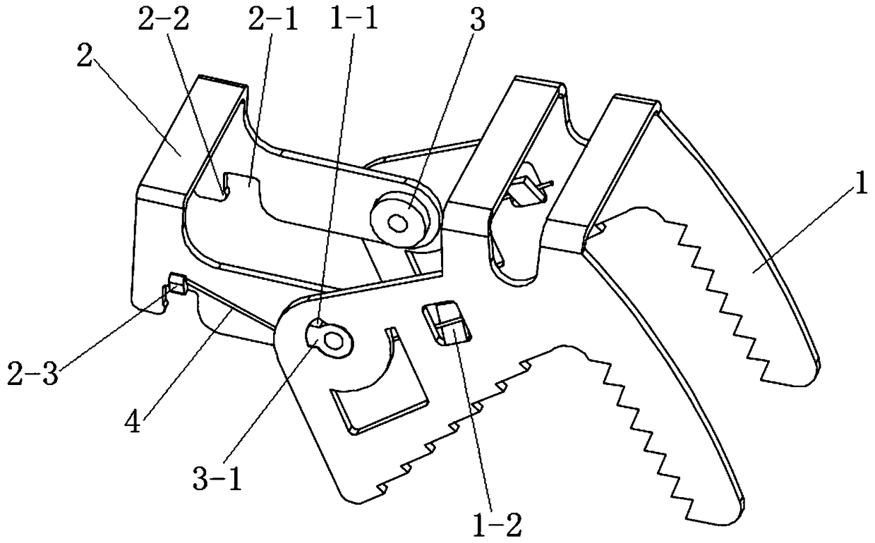
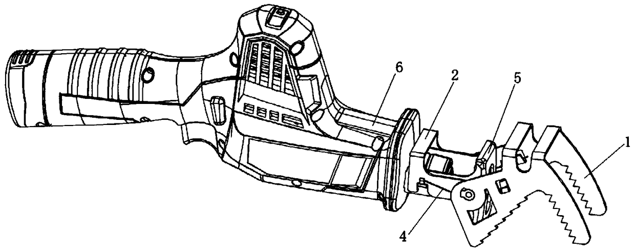
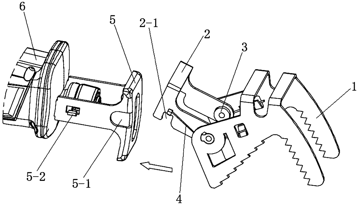
[0037] to combine figure 1As shown, a clamping device for a reciprocating saw in this embodiment is an accessory of an electric reciprocating saw, which can play a role in fixing the reciprocating saw during sawing. It includes a front claw 1, a front claw bracket 2 and an elastic Part 4, the front paw 1 and the front paw support 2 are pivotally hinged, the elastic part 4 is installed between the front paw 1 and the front paw support 2, in order to make the front paw 1 rotate and reset on the front paw support 2, the front paw support 2 The inside front part is provided with the positioning block 3 that can cooperate with the positioning groove 5-1 that is provided with on the stopper frame 5, and the rear portion of the front claw support 2 is provided with the block 5-2 that can be arranged on the stopper frame 5. The card slot 2-1 with the opening facing downward is provided with a hook 2-2 capable of holding the card block 5-2 inside the card slot 2-1. A clamping device f...


PUM


Abstract

The invention discloses a reciprocating saw clamping device and an electric reciprocating saw provided with same, and belongs to the field of electric tools. The reciprocating saw clamping device comprises a front claw, a front claw bracket and an elastic part, wherein the front claw is rotatably hinged with the front claw bracket; the elastic part is mounted between the front claw and the front claw bracket, so that the front claw rotates and returns on the front claw bracket; a positioning block which can be matched with a positioning slot in a tool blocking frame is further arranged on the front part inside the front claw bracket; the rear part of the front claw bracket is equipped with a blocking slot which can be blocked with a blocking block arranged on the tool blocking frame, and is equipped with a downward opening; and a blocking hook which can hook the blocking block is arranged in the blocking slot. The invention further discloses the electric reciprocating saw provided with the clamping device. According to the reciprocating saw clamping device disclosed by the invention, the clamping device can be assembled with the reciprocating saw quicker and more conveniently, so that connection is firmer; moreover, the clamping device is simpler in structure; and a lock catch structure which is connected with the clamping device does not need to be arranged on a reciprocating machine enclosure, so that use is more flexible.

Description

technical field [0001] The invention relates to a hand-held electric tool, more specifically, to a clamping device for a reciprocating saw and an electric reciprocating saw with the clamping device. Background technique [0002] Electric reciprocating saw is a commonly used power tool, mainly used for cutting aluminum profiles, thin iron pipes, PVC plastic pipes and branches, etc. It is widely used in homes, businesses and gardens. The working principle of the electric reciprocating saw is: the motor drives the reciprocating rod to reciprocate through the gearbox, and the saw blade is installed on the reciprocating rod to perform reciprocating sawing movement. [0003] The electric reciprocating saw is a hand-held electric tool, which is very convenient and fast for cutting many workpieces. However, for the sawing of some hard materials, the saw blade reciprocates at high speed relative to the material to be sawed. Under the reaction force, the human body is often The saw b...

Claims


Application Information

Patent Timeline
Patent Type & Authority Patents(China)
IPC IPC(8): B23D49/16B23D51/00
CPCB23D49/16B23D51/00
Inventor 鞠晓峰邵建伟
Owner CHANGZHOU SAIDI TOOLS CO LTD
Learn More