Combing machine

A combing machine and combing technology, applied in the field of combing machines, can solve the problems of inability to visually monitor the material flow and the accessibility of circular combers, etc., and achieve improved visual observation, improved accessibility, and compensation effect of tolerance

Active Publication Date: 2017-03-22
MASCHINENFABRIK RIETER AG
View PDF14 Cites 0 Cited by
  • Summary
  • Abstract
  • Description
  • Claims
  • Application Information

AI Technical Summary

Problems solved by technology

However, the accessibility (eg for cleaning work and assembly work) of this known device to the circular comber (eg for cleaning work and assembly work) from the rear side of the comber is not simple
Furthermore, the visual monitoring of the material flow traveling inside the tong unit cannot be optimally achieved by passing the operator through the tong unit

Method used


Image

  • Combing machine
  • Combing machine
  • Combing machine

Examples


Embodiment Construction

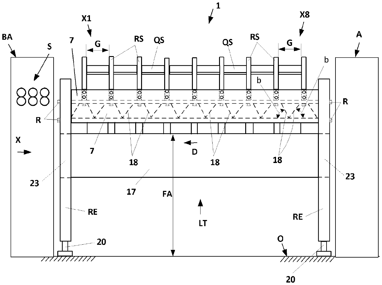
[0028] figure 1 A known embodiment of a combing machine 1 is shown, in which the longitudinal part LT extending between the drive unit A and the sliver laying device BA has a longitudinal beam 8 to which a plurality of combing units X1 to X16 arranged side by side are attached. to the stringer. These combing units generally have smaller dimensions than the combing heads of conventional combing machines, in particular because the combing units are supplied here with only two fiber slivers Z, which are positioned from the longitudinal beam 8 Draw out from the containers F2 to Fx below.

[0029] As shown in FIG. 8 in the publication DE 10 2006 026 841 A1, the combing units X1 to X16 with a width C are arranged directly next to each other and are screwed to the beam 8 . The combing units X1 to X16 each have a housing provided with a corresponding bearing point for supporting the drive shaft driven by the drive unit A.

[0030] The fiber sliver B found on the individual combing ...


PUM

PropertyMeasurementUnit
Radial distanceaaaaaaaaaa

Abstract

The invention relates to a combing machine (1), comprising at least one combing unit (X1 - X16) for combing out fiber material (Z), which is fed to the combing unit in a conveying direction (F), wherein the combing unit has a nipper unit (10), which comprises a lower nipper plate (2) and an upper nipper plate (3) supported movably in relation to the lower nipper plate, and the lower nipper plate (2) has, on a top side thereof, a feed trough (19) with a feeding surface (ZF) arranged upstream, wherein a rotatably supported feed cylinder (9) protrudes into the feed trough, by means of which feed cylinder the fiber material (Z) is fed over a front guiding surface (VF) of a nipper lip (5) attached at the front end of the lower nipper plate (2), which front guiding surface follows the feed trough. In order to improve the accessibility to the top side of the lower nipper plate and of the combing cylinder rotatably supported below the nipper, according to the invention, as viewed against the conveying direction (F) of the fiber material (Z), a rear guiding surface (HF) adjoins the feeding surface (ZF) to the feed trough (19), wherein the feeding surface (ZF) and the rear guiding surface (HF) form an obtuse angle beta and as viewed in the conveying direction (F) of the fiber material (Z), the rear guiding surface (HF) extends in a falling manner at an angle alpha >= 35 degrees in relation to a horizontal plane (E).

Description

technical field [0001] The invention relates to a combing machine with at least one combing unit according to the preamble of claim 1 for combing fiber material supplied to the combing unit in a transport direction. Background technique [0002] Such a comber is known, for example, from EP 1449944 A1, wherein the fiber material supplied to the comber is supplied to nipper units of corresponding combing units (also called combing heads). The ends (fiber tufts) of the fiber material protruding from the closed nipper unit are combed out via the combing section of a circular comber mounted to rotate under the nipper unit. The fiber pack is drawn out of the carded tuft by means of a separating device, in the example shown a separating roller, and bonded to the already formed nonwoven. Due to the substantially horizontal orientation of the lower nipper plate of the nipper unit shown in document EP'944, both for the accessibility for maintenance work in the area of ​​the nipper un...

Claims


Application Information

Patent Timeline
IPC IPC(8): D01G19/16
CPCD01G19/16D01G19/08D01G19/26
Inventor D.博姆梅U.斯图茨
Owner MASCHINENFABRIK RIETER AG
Why Eureka
Try Eureka