Intelligent lighting control system and method

A technology of intelligent lighting control and intelligent control module, which is applied in the direction of energy-saving control technology, lighting devices, light sources, etc., can solve the problems of load flickering, inability to carry out wireless control, increase the complexity of actual installation, etc., and achieve low cost and convenient installation Effect

Inactive Publication Date: 2017-03-22
深圳市英特控科技开发有限公司
View PDF0 Cites 0 Cited by
  • Summary
  • Abstract
  • Description
  • Claims
  • Application Information

AI Technical Summary

Problems solved by technology

[0003] There are two disadvantages of smart switches. The first is that it can only realize simple switching and dimming functions. The second is that the switch wiring is a single live wire system, and the smart switch or the load leaks to get power, which has special requirements for the load. Otherwise It will cause the load to flicker; or a bypass circuit needs to be connected in parallel at both ends of the load, which greatly increases the complexity of the actual installation and hinders the promotion and popularization of intelligent lighting control
[0004] Lamps or light sources are intelligently equipped with mechanical switches, and the mechanical switches are in the form of on and off bistable states, that is, the switch is either in the on state or in the off state, and the off state will completely disconnect the main power supply, and the lamps or light sources will not be powered. The device is offline and cannot be controlled wirelessly

Method used


Image

  • Intelligent lighting control system and method
  • Intelligent lighting control system and method
  • Intelligent lighting control system and method

Examples


Embodiment 1

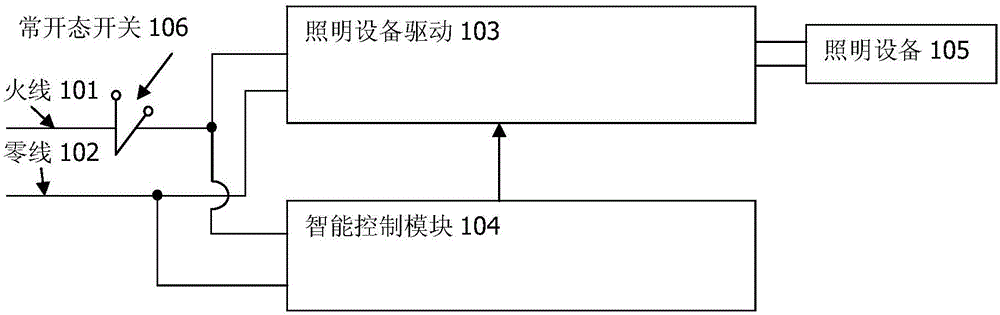
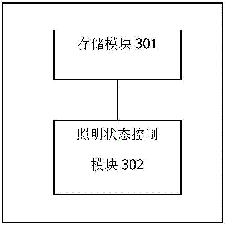
[0042] intelligent control module such as image 3 As shown, it includes a storage module 301 and a lighting state control module 302 . The lighting equipment 105 is in the on state. When the normally-on switch 106 is pressed, the system is powered off, and the intelligent control module is also powered off. After the normally-on switch 106 pops up, the system is powered on, and the intelligent control module is powered on and restarted. The control module 302 reads the state of the lighting device stored in the storage module 301 after power-on and restarting, and it is in the on state, and then outputs an off signal opposite to the on state to the lighting device driver 103, and the lighting device driver 103 turns off the lighting device 105. The lighting state control module 302 then stores the off state in the storage module 301 .

Embodiment 2

[0044] intelligent control module such as Figure 4 As shown, it includes a storage module 401 and a lighting state control module 402 . The storage module 401 is set inside the lighting state control module 402. The lighting equipment 105 is in the off state. When the normally open switch 106 is pressed, the system is powered off, and the intelligent control module is also powered off. After the normally open switch 106 pops up, the system Power on, the intelligent control module is powered on and restarted, and the lighting state control module 402 reads the state of the lighting device stored in the storage module 401 after powering on and restarting, and it is in the off state, and then outputs the on state opposite to the off state to the lighting device driver 103. signal, the lighting device driver 103 turns on the lighting device 105 . The lighting state control module 302 then stores the on state in the storage module 301 .

Embodiment 3

[0046] intelligent control module such as Figure 5 As shown, it includes a power-on detection module 501 , a temporary power supply module 502 , and a lighting state control module 503 . The lighting device 105 is in the off state. When the normally open switch 106 is pressed, the system is powered off, and the temporary power supply module 502 supplies power to the system. The lighting state control module 503 is always in the power supply state. When the normally open switch 106 pops up, When the system is powered on, the power-on detection module 501 sends a power-on signal to the lighting state control module 503, and the lighting state control module 503 reads that the current state of the lighting device from the lighting device driver 103 is an off state, and the lighting state control module 503 sends a signal to the lighting device The driver 103 outputs an on signal, and the lighting device driver 103 turns on the lighting device 105 .


PUM


Abstract

The invention discloses an intelligent lighting control system. The intelligent lighting control system is connected with an lighting equipment driver and a main power supply, and comprises a normally-opened mechanical switch and an intelligent control module; when the normally-opened mechanical switch is pressed, the system is powered off, and when the normally-opened mechanical switch is bounced, the system is powered on; after the intelligent control module is used for powering on the system, a control signal of which the state is opposite to that of current lighting equipment is output to the lighting equipment driver. The invention also discloses a method of intelligent control lighting equipment, and is used for the intelligent lighting control system when the normally-opened mechanical switch is used. The method comprises the following steps: step one, when the normally-opened mechanical switch is pressed, powering off the intelligent lighting control system, and when the normally-opened mechanical switch is bounced, powering on the intelligent lighting control system; and step two, after the intelligent lighting control system is powered on, reversing the state of the current lighting equipment.

Description

technical field [0001] The invention relates to the field of smart home, in particular to a system for intelligently controlling lighting. Background technique [0002] There are currently two directions for intelligent lighting control. The first is to make the switch intelligent, and the lamps and light sources remain unchanged, so that intelligent switching and dimming can be realized. The second is to intelligentize the lamps or light sources, and the traditional mechanical switches on the wall remain unchanged, so that more functions such as color adjustment, color temperature adjustment, and dimming can be realized. [0003] There are two disadvantages of smart switches. The first is that it can only realize simple switching and dimming functions. The second is that the switch wiring is a single live wire system, and the smart switch or the load leaks to get power, which has special requirements for the load. Otherwise It will cause the load to flicker; or a bypass ci...

Claims


Application Information

Patent Timeline
Patent Type & Authority Applications(China)
IPC IPC(8): H05B37/02
CPCH05B47/10Y02B20/40
Inventor 寿健和
Owner 深圳市英特控科技开发有限公司
Why Eureka
Try Eureka