Visual monitoring method for mud-rock flow

A visual monitoring and debris flow technology, applied in image data processing, instruments, calculations, etc., can solve the problems of high cost, poor accuracy, and inconvenient unified monitoring and management, and achieve the effect of reducing operating costs and solving poor monitoring accuracy

Inactive Publication Date: 2017-03-22
CHENGDU TOPPLUSVISION TECH CO LTD
View PDF4 Cites 0 Cited by
  • Summary
  • Abstract
  • Description
  • Claims
  • Application Information

AI Technical Summary

Problems solved by technology

[0005] The technical problem to be solved by the present invention is: to propose a visual monitoring method for debris flow, to solve the problem of real-time performance and poor accuracy caused by manual observation in the debris flow monitoring scheme in the traditional technology and the cost brought by the contact detection method High and inconvenient for unified monitoring and management

Method used


Image

  • Visual monitoring method for mud-rock flow
  • Visual monitoring method for mud-rock flow
  • Visual monitoring method for mud-rock flow

Examples


Embodiment Construction

[0031] The present invention aims to propose a visual monitoring method for debris flow, which solves the problems of poor real-time performance and poor accuracy brought about by manual observation in the debris flow monitoring scheme in the traditional technology and the high cost and inconvenient unification of the contact detection method. monitoring management issues.

[0032] In terms of specific implementation, the visual monitoring method for debris flow in the present invention includes the following implementation steps:

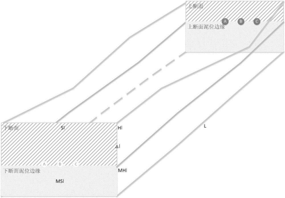
[0033] 1. Deploy a monitoring platform for visual monitoring of debris flow:

[0034] In the present invention, the monitoring platform for visual monitoring includes at least two cameras, and the cameras are fixedly connected. The monitoring platform can be deployed in a fixed location or on an active platform (such as a UAV, etc.). The fixed position is usually selected at a high place far from the debris flow circulation area to ensure that it...


PUM


Abstract

The invention relates to the computer vision and photographing measurement technology and discloses a visual monitoring method for mud-rock flow to solve the problems in the traditional technologies adopted in mud-rock flow monitoring schemes that a manual observation mode often brings poor timeliness and accuracy while a contact type detection mode is often high in cost and is not convenient for unified monitoring and management. The method comprises the following steps: a) deploying a monitoring platform for visual monitoring of the mud-rock flow wherein the monitoring platform comprises at least two cameras; marking the cameras after the deployment of these cameras; b) using the monitoring platform to measure the shape of the circulation area of the mud-rock flow so as to obtain the parameters of the shape prior to the occurrence of the mud-rock flow; and c) conducting real-time monitoring to the circulation area of the mud-rock flow by the monitoring platform; and when a mud-rock flow occurs, based on step b, obtaining the parameters of the circulation area shape of the mud-rock flow as well as the changing amount of these parameters so as to calculate for the mud-rock flow related data. The invention is suitable for mud-rock flow monitoring.

Description

technical field [0001] The invention relates to computer vision and photogrammetry technology, in particular to a visual monitoring method for debris flow. Background technique [0002] Debris flow refers to a special torrent carrying a large amount of sediment and stones due to landslides caused by heavy rain, snowstorm or other natural disasters in mountainous areas or other areas with deep valleys and steep terrain. Debris flow is a common mountain disaster. Its movement process is between landslides, landslides and floods. It is characterized by suddenness, fast flow, large flow, large material capacity and strong destructive power. [0003] my country is a country with frequent occurrence of debris flow disasters, especially during the flood season every year, which often destroy roads, railways and other transportation facilities and even villages and towns, causing large casualties and economic losses to the local area. Therefore, debris flow monitoring technology has...

Claims


Application Information

Patent Timeline
IPC IPC(8): G06T7/62G08B21/10
CPCG08B21/10G06T2207/10016G06T2207/30184
Inventor 张小苗徐一丹周剑龙学军
Owner CHENGDU TOPPLUSVISION TECH CO LTD
Why Eureka
Try Eureka