A Concrete Box Girder Transverse Prestressed Structure

A technology of concrete box girders and prestressed structures, applied in bridges, bridge parts, bridge construction, etc., can solve the problems of little improvement in web crack resistance, increased risk of concrete cracking, and large local tensile stress of concrete, etc., to achieve Increase the effect of lateral prestressing, good application prospects, and simple structure

Active Publication Date: 2018-02-16
DALIAN UNIV OF TECH
View PDF5 Cites 0 Cited by
  • Summary
  • Abstract
  • Description
  • Claims
  • Application Information

AI Technical Summary

Problems solved by technology

There are some problems in this traditional transverse prestressing layout. First, the length of the vertical prestressing steel tendons arranged in the web is limited by the girder height. When the height of the box girder is small, the retraction of the anchorage will make the The stress loss is relatively large, and the effective prestress is greatly reduced, which leads to little improvement of the crack resistance of the web due to the prestress effect; The thickness of the concrete between the anchorage end and the bottom of the beam is not large, and the concrete below the anchorage end will have excessive local tensile stress after the single-end tension of the prestress, which makes the concrete at the lower edge of the web risk tearing; In curved girder bridges, due to the effect of torque, there will also be shear stress in the bottom plate, but this kind of transverse prestress arrangement cannot arrange transverse prestress in the bottom plate due to structural restrictions such as it is difficult to open tension slots on the web. , the risk of concrete cracking of the box girder bottom plate without transverse prestressing is significantly increased compared with the top plate and web plate with transverse prestressing

Method used


Image

  • A Concrete Box Girder Transverse Prestressed Structure
  • A Concrete Box Girder Transverse Prestressed Structure

Examples


Embodiment Construction

[0010] The specific embodiments of the present invention will be described in detail below in conjunction with the technical solutions and accompanying drawings.

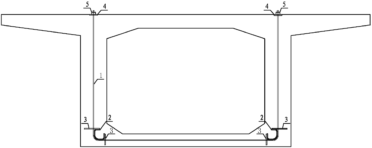
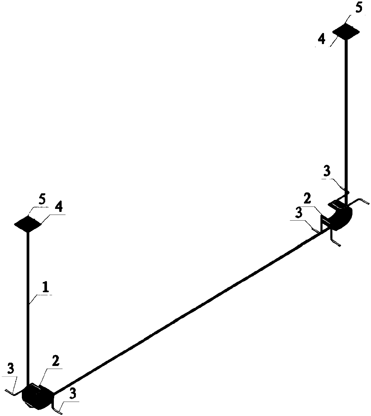
[0011] A concrete box girder transverse bridge direction prestressed structure, the prestressed material adopts unbonded steel strand prestressed steel tendons 1, the number of unbonded steel strands prestressed steel tendons 1 is determined according to the structural design calculation, and the C-shaped The corner angle of the angle steel 2 is determined according to the angle between the web and the bottom plate, and the width is determined according to the number of unbonded steel strand prestressed steel bundles 1, and the prefabricated C-shaped corner steel 2 is set at the junction of the web and the bottom plate It is used to cling to and support the prestressed steel beam 1 of the unbonded steel strand; one side of the U-shaped anti-collapse steel bar 3 is welded with the C-shaped corner steel 2, and the othe...


PUM


Abstract

The invention provides a transverse-bridge-direction prestress structure of a concrete box girder and belongs to the technical field of bridge structure designs. The transverse-bridge-direction prestress structure of the concrete box girder comprises an unbonded steel strand prestress steel tendon, C-shaped angle turning steels, U-shaped anti-collapsing steel bars, anchorage devices and anchorage device base plates. The prestress steel tendon achieves large-angle bending through supporting of the C-shaped angle turning steels arranged at the joints of a web plate and a base plate of the box girder, and an approximate U-shaped arraying shape is formed in the transverse direction of the box girder, so that the transverse prestress effect can be exerted by the wed plate and the base plate at the same time, and overall mechanical performance and anti-crack performance of the concrete box girder are improved. The transverse-bridge-direction prestress structure of the concrete box girder can be widely applied to the field of project designs, the transverse-bridge-direction prestress structure can be adopted in a large-span concrete box girder bridge and a concrete bent girder bridge, and mechanical performance and anti-crack performance of the box girder can be greatly improved.

Description

technical field [0001] The invention belongs to the technical field of bridge structure design, and relates to the design of a prestressed construction mode of a concrete box girder bridge, in particular to a transverse bridge direction prestressed structure in a concrete box girder. Background technique [0002] At present, in the design of long-span prestressed concrete box girder bridges, in order to reduce the main tensile stress of the box girder and at the same time achieve the effect of improving the overall crack resistance of the box girder, the commonly used method is to configure the prestressed steel tendons in the transverse bridge direction. The traditional box girder cross-bridge direction prestressing arrangement mainly adopts finished rolled rebar or steel strand as the prestressing material, and arranges linear prestressing steel beams on the web and roof of the concrete box girder. There are some problems in this traditional transverse prestressing layout....

Claims


Application Information

Patent Timeline
Patent Type & Authority Patents(China)
IPC IPC(8): E01D19/10E01D2/04
CPCE01D2/04E01D19/10
Inventor 姜涛张哲邱文亮黄才良王会利谭岩斌周朋
Owner DALIAN UNIV OF TECH
Why Eureka
Try Eureka