
An external wall connection structure and its construction method

A technology for connecting structures and walls, applied to walls, building components, building structures, etc., can solve problems such as strength, integrity, poor safety, poor wall structure strength, and tight construction time on site, so as to improve integrity and connection strength, connection stability enhancement, and the effect of reducing construction costs

Active Publication Date: 2019-09-27
朱凤起
View PDF7 Cites 0 Cited by
  • Summary
  • Abstract
  • Description
  • Claims
  • Application Information

AI Technical Summary

Problems solved by technology

[0003] 1. The strength of the wall structure is poor;
[0004] 2. The space between the two walls needs to be filled during on-site pouring. The process is time-consuming, and the on-site construction time is tight, the process is simple, and the quality of the poured wall is difficult to guarantee;
[0005] 3. Due to the problems of the pouring material itself or the construction process, the concrete is prone to air bubbles during the pouring process and is not easy to be discharged. After the pouring is completed, many pits will be formed, which will affect the quality of the finished prefabricated wall.
[0006] 4. The material and process of the grouting structure are unstable, time-consuming and labor-intensive, and the strength, integrity, and safety are poor

Method used


Image

  • An external wall connection structure and its construction method
  • An external wall connection structure and its construction method
  • An external wall connection structure and its construction method

Examples


Embodiment Construction

[0040] The present invention will be further described below in conjunction with the accompanying drawings and specific embodiments, so as to help understand the content of the present invention.

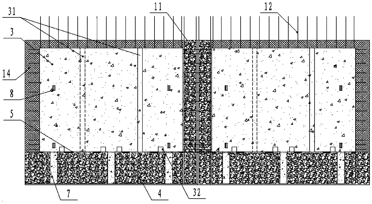
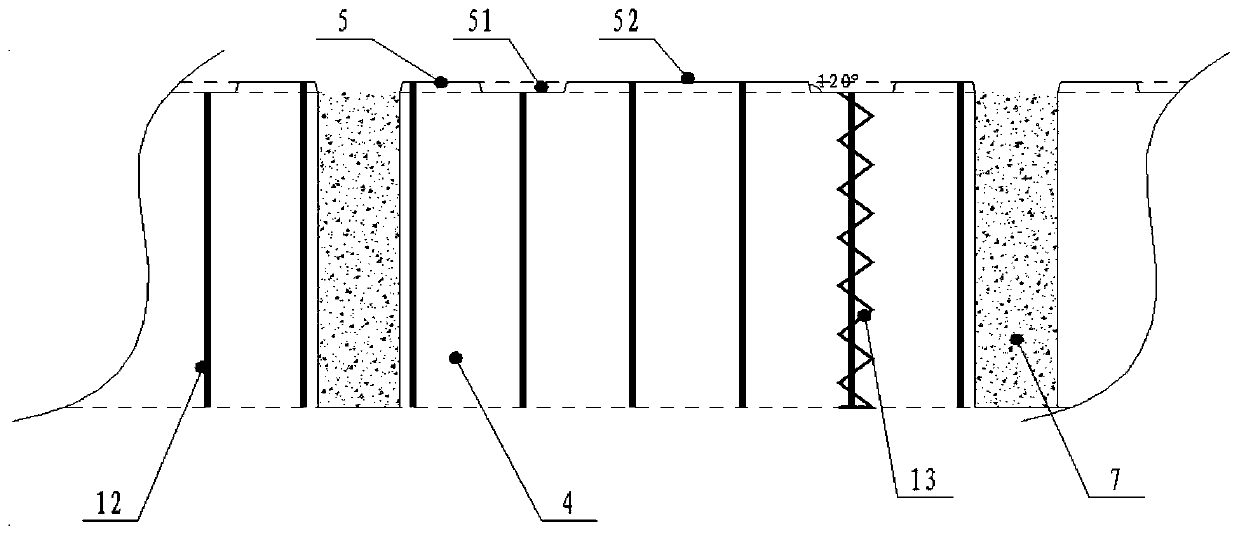
[0041] Such as Figure 1-3 As shown, an external wall connection structure includes prefabricated walls, wherein each prefabricated wall is mainly composed of the first wall 1, the second wall 2 and is sandwiched between the first wall 1 and the second The support body between the walls 2 and the insulation layer 14 are composed; the first wall 1 is an outer leaf wall, the second wall 2 is an inner leaf wall, and the height of the second wall 2 is lower than that of the first wall 1 height, which can form a step for lapping the roof of the interior wall on top. The support body and the insulation layer 14 fit together to form a combined structure, and the two can also be connected by a connector to improve firmness; the height of the insulation layer 14 is basically the same as tha...


PUM


Abstract

The invention discloses an external wall connecting structure. The external wall connecting structure comprises prefabricated walls; each prefabricated wall is at least composed of a first wall body, a second wall body, a support body clamped between the first wall body and the second wall body and a heat preservation layer, wherein spacing is reserved between the bottom of the support body and the bottoms of the first wall body and the second wall body, so that a concrete cast-in-situ space formed between the first wall body and the second wall body is constructed, at least one part of the cast-in-situ space is constructed on the edge of the prefabricated wall, a key groove structure constructed in a connecting plane formed between the support body and the cast-in-situ space comprises key grooves which are evenly distributed at intervals, and the cast-in-situ space communicates with a concrete pouring channel; the external wall connecting structure comprises concrete pouring spaces and cast-in-situ spaces, wherein each concrete pouring space is formed between every two adjacent prefabricated walls, the two prefabricated walls of each cast-in-situ space are constructed on the edge, the concrete pouring spaces communicate with the cast-in-situ spaces of which the prefabricated walls are constructed on the edges, and then the connecting structure which is poured integrally through concrete is formed. According to the external wall connecting structure, the external wall installing integrality and the connecting strength among the walls are greatly improved.

Description

technical field [0001] The invention relates to the field of construction engineering, in particular to an exterior wall connection structure and a construction method for the exterior wall connection structure. Background technique [0002] The wall structure of the existing building comprises two wall bodies arranged at intervals, and a plurality of criss-crossing steel bars are arranged between the two wall bodies, and then poured with concrete to form a complete prefabricated wall body structure. When the two wall structures are combined to form a node, the transverse steel bars of the two need to be bound and then poured. However, since the concrete of the node is poured later, the integrity of the wall connection node is poor, resulting in low strength. Moreover, if the bottom of the wall is not on the same plane, it needs to be filled with mortar to smooth it out. The isolation layer produced by the mortar has poor bonding with the concrete, resulting in a decrease in...

Claims


Application Information

Patent Timeline
Patent Type & Authority Patents(China)
IPC IPC(8): E04B2/84
Inventor 朱凤起
Owner 朱凤起
Learn More