
Robot compliance control method based on contact force observer

A technology of compliant control and contact force, applied in attitude control, three-dimensional position/channel control, etc., can solve problems such as low success rate, limited scope of application, poor adaptability, etc., and achieve the effect of reducing losses and saving development costs

Active Publication Date: 2017-03-08
CENT SOUTH UNIV
View PDF5 Cites 50 Cited by
  • Summary
  • Abstract
  • Description
  • Claims
  • Application Information

AI Technical Summary

Problems solved by technology

There are some problems in the operation of the robot using passive compliance control: (1) The contradiction between the high rigidity and high flexibility of the robot cannot be eradicated
(2) The passive compliance device has strong specificity, poor adaptability, and limited scope of application
(3) It is impossible to make the robot itself react to the force, and the success rate is low, etc.
However, multi-dimensional force sensors are often expensive and easily damaged. For some robots, force sensors cannot be installed

Method used


Image

  • Robot compliance control method based on contact force observer
  • Robot compliance control method based on contact force observer
  • Robot compliance control method based on contact force observer

Examples


Embodiment Construction

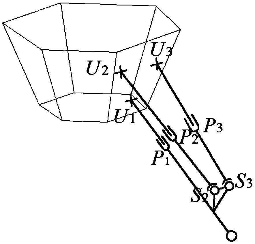
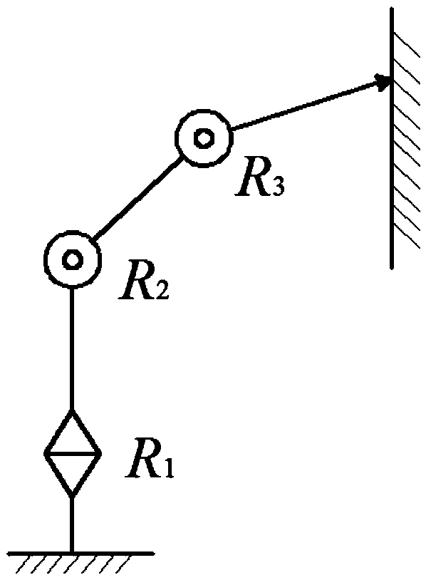
[0026] Hereinafter, the present invention will be further described in detail with reference to the examples and drawings, but the embodiments of the present invention are not limited thereto. This specific embodiment selects a three-degree-of-freedom parallel robot (such as figure 2 Shown) as the target of action, but the implementation target is not limited to this, multi-degree-of-freedom tandem robots (such as image 3 (Shown) also applies.

[0027] The following will describe in detail the principle and implementation of the robot compliance control method based on the contact force observer of the present invention, so that those skilled in the art can understand the robot compliance control based on the contact force observer of the present invention without creative work. method.

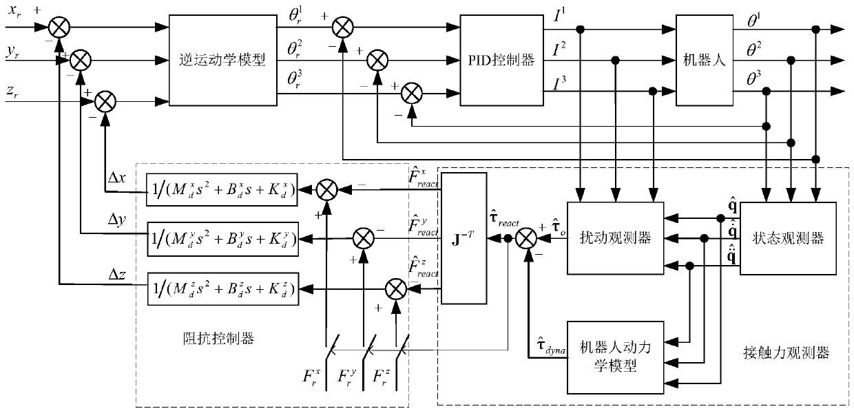
[0028] Such as figure 1 As shown, the present invention provides a robot compliance control method based on a contact force observer specifically including the following steps:

[0029] step 1: ...


PUM


Abstract

The invention discloses a robot compliance control method based on a contact force observer. The robot compliance control method belongs to the field of robot control, does not adopt a force sensor for measuring a contact force of a robot and the environment, but adopts a model for estimating magnitude of the force according to a motion state, and realizes compliance control of the robot by adopting a position-based impedance controller. The robot compliance control method comprises the steps of: acquiring joint angular velocity information by means of an encoder, and estimating an angle, an angular velocity and angular velocity information by means of a state observer; calculating a joint effective driving moment by means of a disturbance observer according to motor current information and joint state information; calculating a joint driving moment required by driving a mechanism to move through adopting a kinetic model according to a joint motion state; and subtracting the driving moment obtained through calculation by adopting the kinetic model from the effective driving moment to obtain a joint driving moment caused by the action of an external force, and mapping the joint driving moment by means of Jacobian matrix to obtain an environmental contact force. The robot compliance control method based on the contact force observer has the advantage that an expensive and easily-damaged multi-dimensional force sensor does not need to be installed.

Description

Technical field [0001] The invention belongs to the field of robot control, and specifically is a robot compliance control method based on a contact force observer, without a multi-dimensional force sensor, and adopts a model estimation method to estimate the contact force as the force feedback of the compliance control to realize the compliance control of the robot. Background technique [0002] Robot compliance control is widely used in cutting, polishing, and assembly operations, as well as in the walking process of walking robots. Compliance control is divided into active compliance control and passive compliance control. The robot relies on some auxiliary compliance mechanisms to make it naturally compliant with external forces when it comes into contact with the environment, which is called passive compliance control; passive compliance mechanisms are the use of some that enable the robot to absorb or store energy when interacting with the environment. Mechanisms such as s...

Claims


Application Information

Patent Timeline
IPC IPC(8): G05D1/08G05D1/10
Inventor 邓华辛桂阳钟国梁王恒生
Owner CENT SOUTH UNIV
Learn More