
Air pipe unit joint structure

A unit connection and connection head technology, which is applied in the field of air duct unit connection head structure, can solve the problems of reducing the comfort of the residential environment temperature, uneven cooling/heating of the space, and uneven heating and cooling of the temperature area, so as to improve the convenience of installation Excellent performance and applicability, convenient and fast card connection, and the effect of reducing wind loss

Inactive Publication Date: 2017-03-08
CHONGQING UNIV
View PDF7 Cites 2 Cited by
  • Summary
  • Abstract
  • Description
  • Claims
  • Application Information

AI Technical Summary

Problems solved by technology

[0003] In traditional residential air conditioners, the air supply mode is generally to spray air from the air outlet. The temperature near the air supply outlet is relatively low, and the temperature away from the air supply outlet is relatively high, resulting in uneven cooling / heating of the space.
Therefore, the traditional household jet air conditioner needs to spend more time and energy to make the whole space reach the set temperature everywhere.
Moreover, the air supply from the air outlet causes the temperature area in the house to be uneven, and the wind flow in the area directly facing the air outlet is greatly disturbed, which greatly reduces the comfort of the residents to the ambient temperature of the house.

Method used


Image

  • Air pipe unit joint structure
  • Air pipe unit joint structure
  • Air pipe unit joint structure

Examples


Embodiment approach

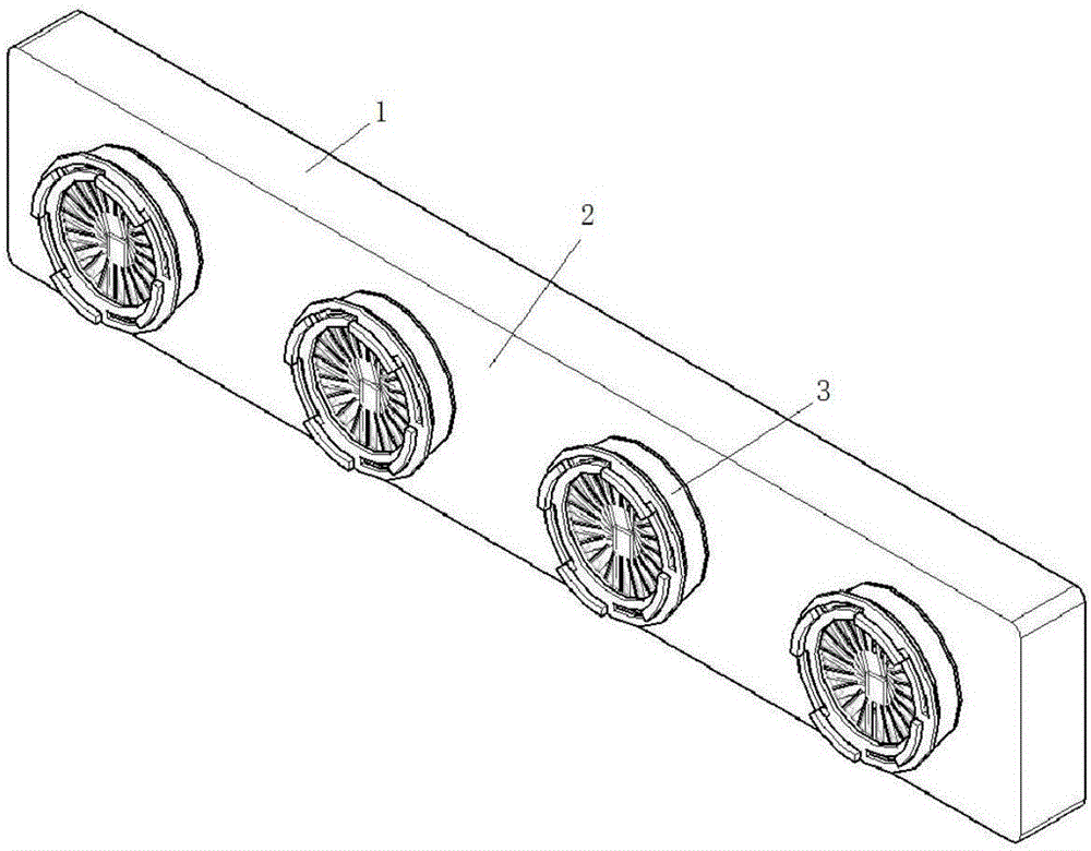
[0030] The optimal implementation mode: if Figure 1-7As shown, a residential temperature control air outlet system adopting the structure of the present invention includes an air confluence box 1 connected to the air outlet of the air conditioning system, and the air confluence box 1 has an air outlet side 2 provided with an air outlet , the air outlet is connected with an air outlet duct extending outward away from the wind confluence box, and an air volume adjustment mechanism is also arranged between the air outlet and the air outlet duct, the end of the air outlet duct is closed, and the circumferential wall It has a ventilation structure that can realize circumferential ventilation.

[0031] In this way, after the above system is installed, the air from the air outlet of the air conditioner can be guided into the air outlet pipe, and then leak out from the surrounding wall of the air outlet pipe. The defects caused by heat unevenness and large wind disturbance improve t...


PUM


Abstract

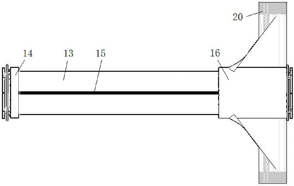
The invention discloses an air pipe unit joint structure. The air pipe unit joint structure comprises a cylindrical joint body and is characterized by further comprising an air volume regulation mechanism; the air volume regulation mechanism comprises a cylindrical fixed regulation ring; a plurality of sets of blade structures are uniformly arranged in the fixed regulation ring in the circumferential direction; each blade structure comprises a blade and a cross rod formed by perpendicularly and fixedly connecting a short rod and a long rod, the short rod of the cross rod is perpendicular to the blade and is mounted in the fixed regulation ring in a matched mode in the axial direction of the fixed regulation ring, the short rod is provided with a rotary pair, and other moving pairs are restrained by the fixed regulation ring; an annular regulation rotary ring is rotatably connected to the fixed regulation ring in a sleeved and matched mode; and the inner surface of the regulation rotary ring is engaged with the short ends of the long rods to drive the long rods to rotate along the short rods. The air pipe unit joint structure has the advantages that the structure is simple, the air flow can be regulated conveniently, and air flow loss can be reduced.

Description

technical field [0001] The invention relates to a fiber fabric air duct unit in the field of residential temperature control equipment, in particular to a joint structure of the air duct unit. Background technique [0002] At present, residential temperature control equipment generally includes air conditioning, floor heating, electric heating, etc.; however, the most widely used air conditioning system is used to regulate the temperature of the residential environment by the cold or hot air sent by the air conditioner for cooling or heating. [0003] The air supply mode of traditional residential air conditioners is generally to spray air from the air outlet. The temperature near the air supply outlet is relatively low, and the temperature away from the air supply outlet is relatively high, resulting in uneven cooling / heating of the space. Therefore, it takes more time and energy consumption to make the entire space reach the set temperature everywhere in the traditional ho...

Claims


Application Information

Patent Timeline
Patent Type & Authority Applications(China)
IPC IPC(8): F24F13/02F24F13/14
CPCF24F13/0209F24F13/142
Inventor 串禾念韬杰秦士奇曹益坚郑洁
Owner CHONGQING UNIV
Learn More