Pulverizing device for fan and fan comprising pulverizing device

A crushing device and fan technology, which is applied in road cleaning, grain processing, construction, etc., can solve the problems of affecting the suction power of the fan, troublesome configuration and installation, and many production processes, so as to achieve good crushing and suction effects and easy disassembly and assembly And maintenance, crushing effect is good

Inactive Publication Date: 2017-03-08
青岛中汽特种汽车有限公司
View PDF7 Cites 5 Cited by
  • Summary
  • Abstract
  • Description
  • Claims
  • Application Information

AI Technical Summary

Problems solved by technology

[0003] At present, the road sweeper fans on the market only have the suction function and do not have the crushing function. When sucking large materials such as fallen leaves, it is easy to cause the clogging of the volute, which affects the suction force of the fan.
[0004] Even if the fan has the function of crushing, most of the fans and crushing devices are separated from each other, or exist on different devices or are different structures independently installed on the same device. The structure is complicated and needs to be completed in two operations, which leads to many inconveniences such as large equipment investment, troublesome configuration and installation, and many production processes.

Method used


Image

  • Pulverizing device for fan and fan comprising pulverizing device
  • Pulverizing device for fan and fan comprising pulverizing device
  • Pulverizing device for fan and fan comprising pulverizing device

Examples


Embodiment Construction

[0020] Combine below Figure 1 to Figure 3 The pulverizing device for the fan of the present invention and the fan with the pulverizing device are described in further detail.

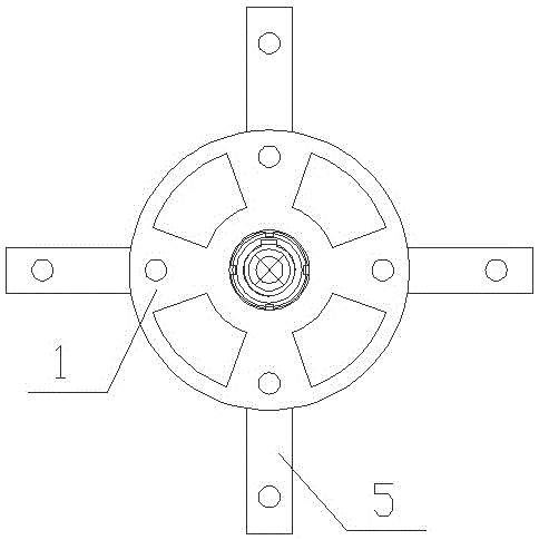
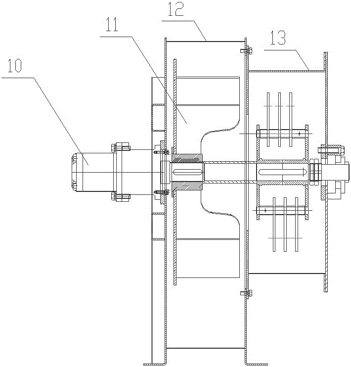
[0021] Such as figure 1 with figure 2 As shown, the crushing device for a fan of the present invention mainly includes a shaft sleeve 1, a rotating disk end plate 2, a connecting shaft 3, a crushing blade 5, and a transmission shaft 9.

[0022] The shaft sleeve 1 and the rotating disk end plate 2 together constitute the rotating disk, the shaft sleeve 1 is a ring body, the rotating disk end plate 2 is a disc shape, and the shaft sleeve 1 is fixed at the center of one end surface of the rotating disk end plate 2. The rotating disk The weight-reducing holes are evenly distributed on the end plate 2.

[0023] The rotating disc is a pair, and the two rotating discs are distributed symmetrically. The end of the sleeve 1 that is not connected to the end plate 2 of the rotating disc is the symmetry plane. The end ...


PUM


Abstract

The invention relates to a pulverizing device for a fan and the fan comprising the pulverizing device, and solves problems that the conventional fan is incomplete in function, complicated in equipment, easy to block a volute casing, and easy to damage. The pulverizing device comprises rotating disks, connecting shafts, spacer bushes and pulverizing blades, wherein the rotating disks are disk-like bodies having annular sleeves at centers; the rotating disks are arranged in pairs by using one end surface of the sleeve as a symmetrical plane; a plurality of connecting shafts are arranged between opposite sides of the rotating risks; the connecting shafts are fixed on the two rotating disks; a plurality of pulverizing blades sleeve the connecting shafts; the spacer bushes are arranged between each pulverizing blade and each rotating disk and between the pulverizing blades; the spacer bushes are fixedly connected with the connecting shafts. The pulverizing device has advantages of simple structure, assembly / disassembly and maintenance convenience, is used in coordination with the fan, can pulverize while suction so as to avoid fan blocking phenomenon and influence on suction wind, has good pulverization and suction effects and high efficiency, is not easy to damage, and has long duration of work and small interference.

Description

Technical field [0001] The invention relates to a crushing device, in particular to a crushing device for a fan. Background technique [0002] As a typical model and key application tool of urban sanitation vehicles, road sweepers have been well developed, and various technologies have become mature. The fan is a key component of the road sweeper. [0003] The current sweeper fans on the market only have a suction function, but do not have a crushing function. When sucking large materials such as fallen leaves, it is easy to cause the volute blockage and affect the suction power of the fan. [0004] Even if the fan has a crushing function, most fans and crushing devices are separated from each other, or exist on different equipment or have different structures independently set up on the same equipment. When these two functions are required at the same time, it is inevitable that there will be many equipment and equipment. The complex structure and the need to complete the operatio...

Claims


Application Information

Patent Timeline
Patent Type & Authority Applications(China)
IPC IPC(8): E01H1/08B02C18/18B02C23/24
CPCE01H1/08B02C18/18B02C23/24B02C2201/06E01H2001/0881
Inventor 纪建奕张世功王伟郑招强彭修强步广超王传远纪国清
Owner 青岛中汽特种汽车有限公司
Why Eureka
Try Eureka