Modal parameter test method of rigid body of power assembly suspension system based on full-automobile states

A powertrain and rigid body modal technology, which is applied to vehicle suspension/shock absorber testing and other directions, can solve the problems of non-simultaneous acquisition of frequency response function data, loss of modal identification, and irrelevance of frequency response function consistency. Avoids irrelevant effects of FRF consistency

Active Publication Date: 2017-03-01
SOUTH CHINA UNIV OF TECH
View PDF6 Cites 9 Cited by
  • Summary
  • Abstract
  • Description
  • Claims
  • Application Information

AI Technical Summary

Problems solved by technology

There are mainly two types of artificial excitation: vibrator excitation and hammer excitation. With vibrator excitation, the mode of the structure may be essentially affected by the mass and stiffness of the vibrator attachment, and if only one vibrator is used Excitation, if the excitation position is at the node of a certain mode, the mode will be lost in the mode identification
[0006] The artificial excitation modal method mainly has three directions for hammering excitation and single-point hammering excitation respectively. The hammering in the three direct

Method used


Image

  • Modal parameter test method of rigid body of power assembly suspension system based on full-automobile states
  • Modal parameter test method of rigid body of power assembly suspension system based on full-automobile states
  • Modal parameter test method of rigid body of power assembly suspension system based on full-automobile states

Examples


Embodiment Construction

[0033] Hereinafter, the present invention will be described in detail by taking the power assembly of the three-point suspension system as an example, with reference to the accompanying drawings and specific embodiments.

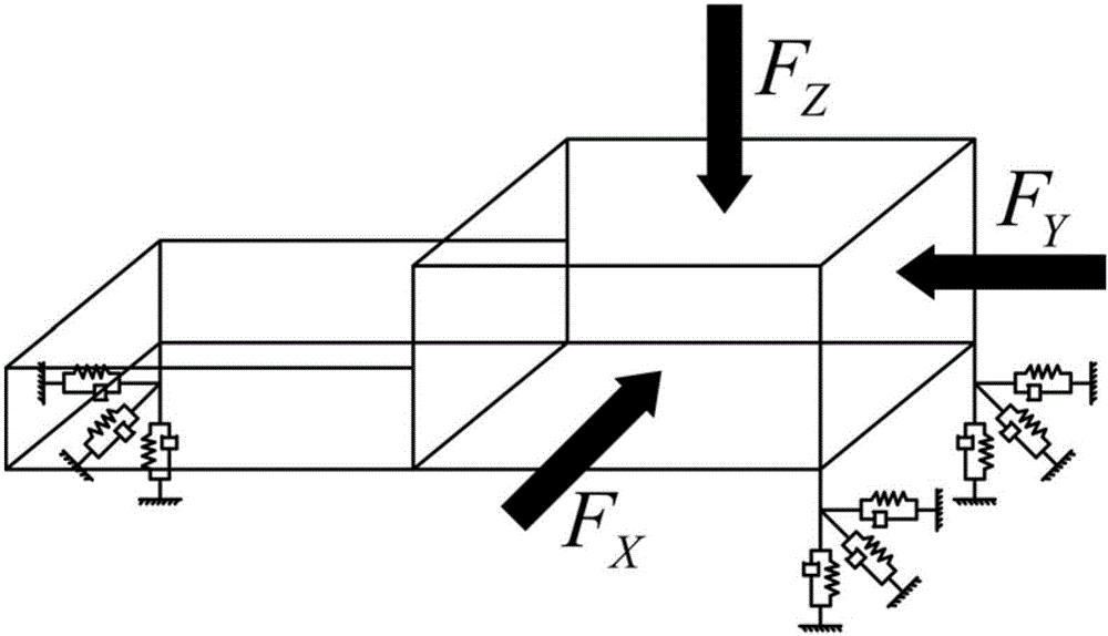
[0034] A test method for the rigid body modal parameters of the powertrain suspension system in the vehicle state. The test method is to use the rubber soft hammer head of the counterweight as the hammer excitation, and take the direction of the vehicle coordinate system as the reference: the X axis points to the rear of the vehicle Perpendicular to the front axis, the Z axis is vertically upward, and the Y axis is determined according to the right-hand rule; figure 1 As shown, taking the powertrain of the three-point suspension system as an example, the six free rigid body modes (translation in three directions and rotation in three directions) are divided into three groups, and each group is subjected to a separate modal parameter Identification; the speci...


PUM


Abstract

The invention discloses a modal parameter test method of a rigid body of a power assembly suspension system based on full-automobile states. According to the test method, a counter-weight based rubber soft hammerhead is used for force hammer excitation and a full-vehicle coordinate system is used as the reference; the X axis points to the back of the vehicle and is perpendicular to the front shaft; the Z axis is upwards vertical; the Y axis is determined according to the right hand rule; the six-degree-of-freedom rigid body modal including translational motions in three directions and rotation around three directions into three groups, and single modal parameter identification is performed on each group once; the specific steps are: selecting X-direction excitation FX of the power assembly, testing frequency response functions of response points and using the PolyMAX modal identification method to identify the X-direction transitional motion modal and rotation modal around the Y axis and the Z axis; selecting Y-direction excitation FY and identifying Y-direction transitional motion modal and rotation modal around the X axis and the Z axis; and selecting Z-direction excitation FZ and identifying Y-direction transitional motion modal and rotation modal around the X axis and the Y axis. According to the invention, the test method is simple to operate, high in identification accuracy and suitable for identification of six-degree-of-freedom modal parameters of the rigid body of any rubber support.

Description

technical field [0001] The invention belongs to the field of automobile loading performance testing, and relates to a testing technology for a power assembly mounting system of an automobile, in particular to a method for testing rigid body modal parameters of a power assembly mounting system in a complete vehicle state. Background technique [0002] Rigid body modal frequency and decoupling rate of automotive powertrain mount system are important parameters for mount system design, and also important evaluation indicators for powertrain vibration isolation performance. [0003] At present, the modal parameters of the vehicle powertrain mount system are mainly based on theoretical calculation and simulation analysis in the early stage of vehicle development. Due to factors such as the manufacturing error of the suspension product and the constraints of the vehicle, there are differences between the theoretical modal parameters and the real modal parameters in the vehicle sta...

Claims


Application Information

Patent Timeline
IPC IPC(8): G01M17/04
CPCG01M17/04
Inventor 陈涛李巍华叶鸣陈祝云
Owner SOUTH CHINA UNIV OF TECH
Why Eureka
Try Eureka