rotating electrical machine

A technology for rotating motors and rotors, which is applied to electrical components, electromechanical devices, and electric components. It can solve problems such as increased workload, shedding of balance weights, and increased corrections, and achieve the effect of preventing accidental movement of keys.

Inactive Publication Date: 2018-04-10
MITSUBISHI ELECTRIC CORP
View PDF8 Cites 0 Cited by
  • Summary
  • Abstract
  • Description
  • Claims
  • Application Information

AI Technical Summary

Problems solved by technology

[0003] However, since the unbalance of individual parts such as the shaft and the iron core is corrected collectively, there is a problem that the correction amount in the entire rotor increases and the workload increases.
In addition, due to the increase of the balance weight and the lack of riveting amount accompanying the balance weight, problems such as the fall of the balance weight also occurred.

Method used


Image

  • rotating electrical machine
  • rotating electrical machine
  • rotating electrical machine

Examples


Embodiment approach 1

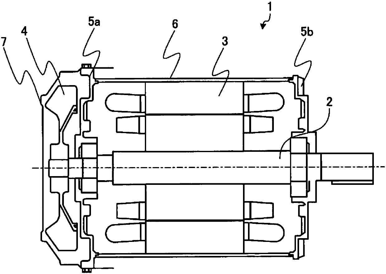
[0056] figure 1It is a figure which shows the cross-sectional shape of Embodiment 1 of the rotating electric machine concerning this invention. The rotating electrical machine 1 is composed of a rotor 2 and a stator 3 , and an external fan 4 is attached to one side of the rotor 2 for cooling the heat generated by the rotating electrical machine 1 . Brackets 5 a and 5 b and a frame 6 are attached to the outside of the stator 3 , and a fan cover 7 is attached to the outside of the external fan 4 .

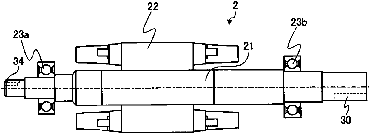
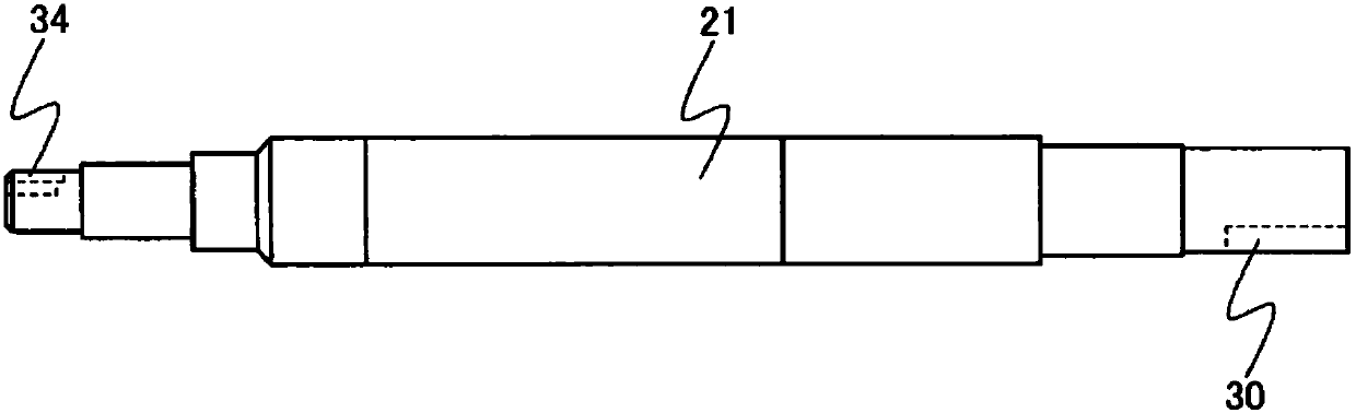
[0057] figure 2 It is a figure which shows the structure of a rotor. The rotor 2 is constructed such that a shaft 21 passes through the center of an iron core 22, and they are held by bearings 23a, 23b. image 3 It is a figure showing the structure of the shaft. On the P side of the shaft 21, a key groove 30 for inserting a key for coupling with a coupling or a mechanical device is engraved. In addition, on the O side of the shaft 21, a key groove 34 into which a key for coupli...

Embodiment approach 2

[0077]Regarding Embodiment 1, in the step of machining the key groove of the shaft, two key grooves having different widths must be produced. For this reason, it is necessary to prepare tools with different sizes when milling the key groove, and the complexity of the work increases. In Embodiment 2, a method realized by using grooves of the same width will be described.

[0078] Figure 29 , Figure 30 as well as Figure 31 It is an enlarged view of the end portion of the shaft on the O side of Embodiment 2 of the rotating electric machine according to the present invention, Figure 29 for top view, Figure 30 main view, Figure 31 for side view. The key groove 36 has a shape in which, in addition to the shallow groove 361 having a first depth as a key fitting groove, it has the same width as the shallow groove 361 and a second depth deeper than the first depth as a balance adjustment. The groove is provided with a deep groove 362 . The depth of the key groove 36 is ar...


PUM


Abstract

This rotating electrical machine is provided with one end having a first shaft diameter and another end having a second shaft diameter greater than the first shaft size, a rotor being formed using a shaft (21) to one end of which a key groove (34) is provided, wherein the key groove (34) has: a shallow groove (341) as a key fitting groove of a first depth in which a key is fitted; and a deep groove (342) as a balance adjustment groove formed in a manner so as to have a second depth deeper than the first depth and resulting from a partial region of the bottom surface of the shallow groove (341) being dug deeper. Balance adjustment has already been implemented at the shaft (21) alone, so in addition to being able to reduce the man-hours involved in balance correction of the entire rotor, it is possible to prevent the key from inadvertently moving.

Description

technical field [0001] The invention relates to a rotating electric machine. Background technique [0002] In a rotating electric machine, if the center of gravity of the rotor deviates from the rotating shaft, it will cause vibration or the like, and therefore high-precision balance correction is required. The rotor of a rotating electrical machine consists of a shaft, iron core, bearings, etc., and conventional balance corrections have been performed by riveting a weight as a balance weight to the end ring joining portion after the rotor is completed. [0003] However, since the unbalance of individual components such as the shaft and the core is collectively corrected, there is a problem that the amount of correction in the entire rotor increases and the workload increases. In addition, due to the increase in the weight of the balance weight and the lack of the amount of caulking associated with the balance weight, problems such as the fall of the balance weight also occ...

Claims


Application Information

Patent Timeline
Patent Type & Authority Patents(China)
IPC IPC(8): H02K7/00
CPCH02K7/00
Inventor 杉山昌伸原川雅哉
Owner MITSUBISHI ELECTRIC CORP
Why Eureka
Try Eureka