Photosensitizers and Photoelectric Conversion Elements
A technology for photoelectric conversion elements and photosensitizers, applied in the fields of photosensitizers and photoelectric conversion elements, can solve the problems that conversion efficiency and durability have not yet reached a practical level, and achieve improved photoelectric conversion efficiency, improved adsorption stability, and high molar absorption coefficient. Effect
- Summary
- Abstract
- Description
- Claims
- Application Information
AI Technical Summary
Problems solved by technology
Method used
Image
Examples
Embodiment 1
[0166]
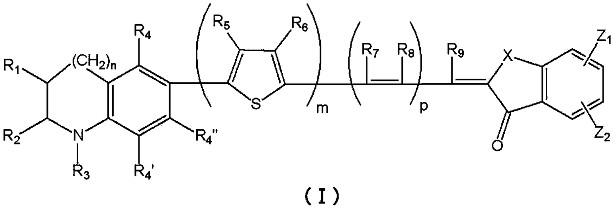
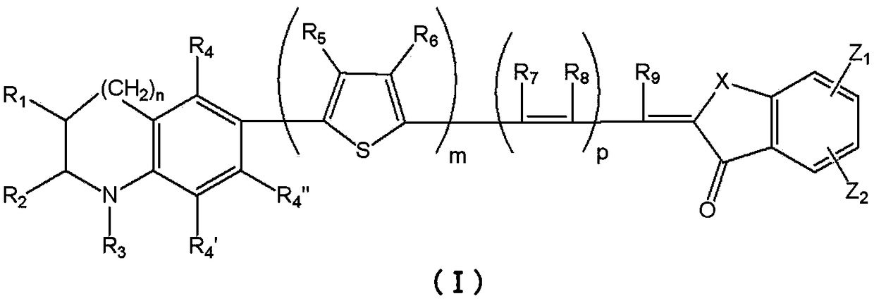
[0167] Aldehyde (B-01) (0.88 g) and intermediate (C-01) (0.50 g) were dissolved in acetic acid (10 mL), and heated and stirred at 100° C. for 4 hours. The reaction mixture was cooled to room temperature and solidified. The crude crystals were separated by filtration, and were separated by column chromatography (silica gel, developer: CHCl 3 / MeOH=100 / 1) was separated and purified, whereby 0.85 g of a pigment (I-03) was obtained as a brown solid (69% yield). λmax=545nm (CHCl 3 ).
[0168] The structure of the obtained pigment (I-03) was identified by NMR analysis.
[0169] 1 H NMR (400MHz, DMSO-d 6 )
[0170] δ (ppm) = 13.65 (1H, br.s), 8.67 (1H, br.s), 8.33 (1H, dd, J = 8.0, 7.6Hz), 8.24 (1H, d, J = 11.6Hz), 8.20 (1H,br.s),7.94(1H,dd,J=7.6,7.6Hz),7.65(1H,s),7.41-7.49(3H,m),7.30-7.38(5H,m),7.19-7.23 (4H,m),7.11(1H,s),7.07(2H,d,J=8.4Hz),6.87(1H,d,J=8.8Hz),5.07-5.11(1H,m),3.82-3.87( 1H,m),2.03-2.12(1H,m),1.69-1.83(2H,m),1.59-1.67(2H,m),1.27-1.38(1H,m)
Embodiment 2
[0171]
[0172] Using the same method as in Example 1, and using an aldehyde intermediate (B-02), a pigment (I-05) was obtained as a black solid. λmax=541nm (CHCl 3 ).
[0173] The structure of the obtained pigment (I-05) was identified by NMR analysis.
[0174] 1 H NMR (400MHz, DMSO-d 6 )
[0175] δ(ppm)=13.63(1H,br.s),8.72(1H,br.s),8.35(1H,d,J=8.0Hz),8.28(1H,br.s),8.25(1H,d, J=11.6Hz),7.95(1H,dd,J=8.0,7.6Hz),7.90(1H,d,J=8.4Hz),7.83(1H,d,J=7.2Hz),7.69(1H,s) ,7.67(1H,d,J=1.6Hz),7.56(1H,d,J=7.2Hz),7.41(1H,dd,J=8.0,1.2Hz),7.36(1H,dd,J=8.0,7.2 Hz), 7.32(1H,dd,J=8.4,7.2Hz),6.87(1H,d,J=8.4Hz),5.24-5.27(1H,m),3.90-3.94(1H,m),2.08-2.18 (1H,m),1.74-1.88(3H,m),1.64-1.73(1H,m),1.50(3H,s),1.47(3H,s),1.37-1.53(1H,m)
Embodiment 3
[0176]
[0177] Using the same method as in Example 1, and using an aldehyde intermediate (B-03), a pigment (I-06) was obtained as a black solid. λmax=546nm (CHCl 3 ).
[0178] The structure of the obtained pigment (I-06) was identified by NMR analysis.
[0179] 1 H NMR (400MHz, DMSO-d 6 )
[0180] δ (ppm) = 13.07 (1H, br.s), 8.17 (1H, br.s), 7.81 (1H, dd, J = 7.6, 7.2Hz), 7.73 (2H, d, J = 9.6Hz), 7.41 (1H,d,J=8.0Hz),7.34(1H,d,J=8.4Hz),7.27(1H,d,J=7.2Hz),7.14(1H,s),6.99(1H,s),6.92 (1H,d,J=6.8Hz),6.88(1H,d,J=8.0Hz),6.83(1H,dd,J=7.2,6.0Hz),6.80(1H,dd,J=7.2,6.4Hz) ,6.30(1H,d,J=8.4Hz),4.72-4.75(1H,m),3.36-3.40(1H,m),1.57-1.65(1H,m),1.43-1.56(4H,m),1.28 -1.35(1H,m),1.11-1.26(3H,m),0.84-0.95(1H,m),0.45-0.59(4H,m),0.16(3H,t,J=7.2Hz),0.10(3H ,t,J=7.2Hz),0.02-0.04(4H,m)
PUM
 Abstract
Description
Claims
Application Information
 - R&D Engineer
- R&D Manager
- IP Professional
- Industry Leading Data Capabilities
- Powerful AI technology
- Patent DNA Extraction
Browse by: Latest US Patents, China's latest patents, Technical Efficacy Thesaurus, Application Domain, Technology Topic, Popular Technical Reports.
© 2024 PatSnap. All rights reserved.Legal|Privacy policy|Modern Slavery Act Transparency Statement|Sitemap|About US| Contact US: help@patsnap.com


