
Detection circuit, gate drive circuit and display panel

A gate drive circuit and detection circuit technology, applied in the direction of static indicators, instruments, etc., can solve the problems that the position cannot be quickly determined, the display panel is difficult, and the specific position of the defect cannot be accurately determined, so as to achieve accurate statistics Effect

Active Publication Date: 2017-02-22
BOE TECH GRP CO LTD +1
View PDF7 Cites 23 Cited by
  • Summary
  • Abstract
  • Description
  • Claims
  • Application Information

AI Technical Summary

Problems solved by technology

However, due to the influence of the thin film transistor itself and other external factors, this part is prone to defects and damages during the production process.
Due to the large number of gate drive units in the display panel, the location of the defect cannot be quickly determined, which brings difficulties to in-depth analysis and further repair of the display panel
[0003] The traditional method of detecting the location of the above defects is mainly to detect the signal by protruding the test metal pattern from the last gate drive unit, but it cannot accurately determine the specific location of the defect on the screen.

Method used


Image

  • Detection circuit, gate drive circuit and display panel

Examples


Embodiment Construction

[0044] Specific embodiments of the present invention will be described in detail below in conjunction with the accompanying drawings. It should be understood that the specific embodiments described here are only used to illustrate and explain the present invention, and are not intended to limit the present invention.

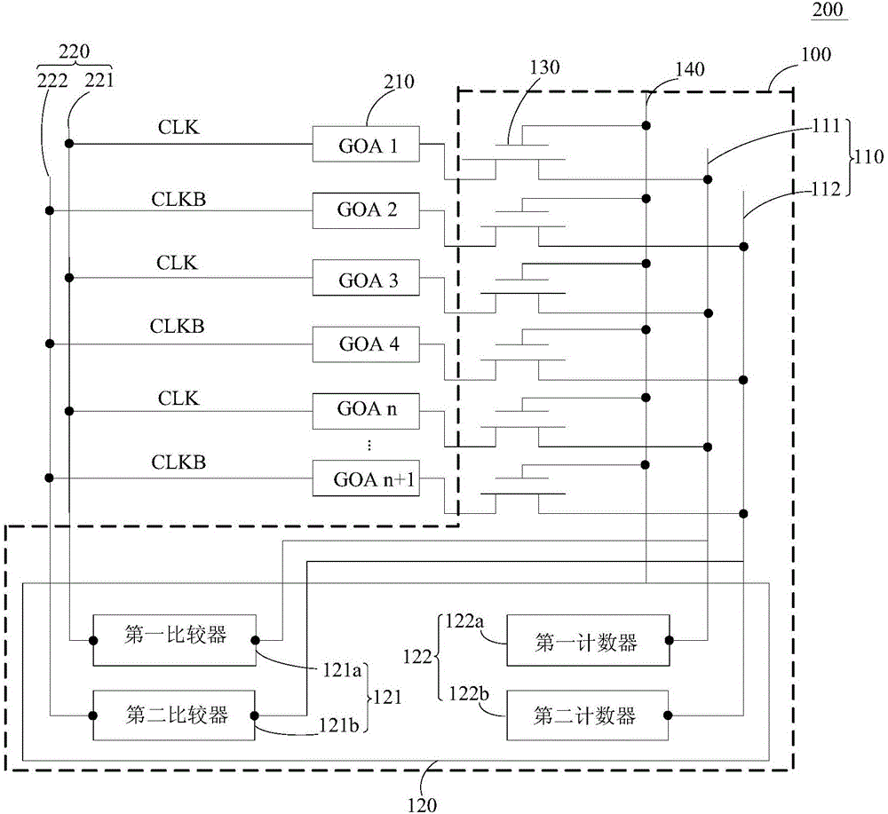
[0045] refer to figure 1 , the first aspect of the present invention relates to a detection circuit 100 for detecting the gate drive circuit 200 . Wherein, the gate drive circuit 200 includes cascaded shift register units 210, and at least one set of clock signal lines 220, each set of clock signal lines 220 includes at least one clock signal line, and the clock signal line 220 is a cascaded shift register unit 220. Register unit 210 provides a clock signal.

[0046] The above detection circuit 100 includes at least one detection signal line 110 and a detection control module 120 . Wherein, each clock signal line 220 corresponds to a detection signal line 110...


PUM


Abstract

The invention discloses a detection circuit, a gate drive circuit and a display panel. The detection circuit is used for detecting the gate drive circuit and comprises at least one detection signal line and a detection control module; each clock signal line is corresponding to a detection signal line; the detection signal line is connected with an output end of a shift register unit; the detection control module comprises a clock signal input end and a detection signal input end; the clock signal input end is connected with each group of clock signal lines; the detection signal input end is connected with the detection signal line; the detection control module is used for comparing to determine whether the clock signal input into the shift register unit is consistent with the input signal input into the detection control module by the detection signal line corresponding to the clock signal line; and if the clock signal is inconsistent with the input signal, the detection control module outputs a fault signal. The shift register unit can be conveniently detected, the yield of the gate drive circuit is accurately judged, and the cost is saved.

Description

technical field [0001] The present invention relates to the field of display technology, in particular to a detection circuit, a gate drive circuit including the detection circuit, and a display panel including the gate drive circuit. Background technique [0002] With the development of the display industry, the resolution of the display panel screen is required to be higher and higher, so the display panel tends to be designed with narrow borders, so that the technology of gate drive (ie, GOA) implemented by the thin film transistor itself is widely used. However, due to the influence of the thin film transistor itself and other external factors, this part is prone to defects and damages during the production process. Due to the large number of gate driving units of the display panel, the location of the defect cannot be quickly determined, which brings difficulties for in-depth analysis and further repair of the display panel. [0003] The traditional method of detecting...

Claims


Application Information

Patent Timeline
Patent Type & Authority Applications(China)
IPC IPC(8): G09G3/00G09G3/20
CPCG09G3/006G09G3/20
Inventor 孙丽李红敏王迎陶健
Owner BOE TECH GRP CO LTD
Learn More