
3d film fixture

A film and jig technology, applied in packaging and other directions, can solve problems such as affecting the effect of lamination, affecting the effect of lamination, contaminating mobile phone cases, etc., to improve accuracy and production efficiency, improve the stability of lamination, avoid The effect of folds and bubbles

Active Publication Date: 2018-12-28
SHENZHEN HANJIANG AUTOMATION SCI & TECH CO LTD
View PDF5 Cites 0 Cited by
  • Summary
  • Abstract
  • Description
  • Claims
  • Application Information

AI Technical Summary

Problems solved by technology

[0003] The protective film is generally pasted manually, the work efficiency of the film is low, the cost is high, and the accuracy of the lamination cannot be guaranteed. Moreover, when the film is peeled off from the backing paper or the material tape, there is a problem of manual stripping due to uneven force. The problem of broken diaphragm affects the effect of subsequent lamination. Further, in repeated manual operations, the mobile phone case or diaphragm is often polluted by the residual glue on the hands of the operator, which will also affect the subsequent bonding. fit effect
[0004] At present, there are laminating equipment on the market that can automatically complete the work of pasting films, but mainly for flat tempered films, these devices cannot laminate films on 3D glass

Method used


Image

  • 3d film fixture
  • 3d film fixture
  • 3d film fixture

Examples


Embodiment Construction

[0022] The application will be further described in detail below in conjunction with the drawings and specific embodiments. It should be understood that the following exemplary embodiments and descriptions are only used to explain the present invention, not as a limitation to the present invention, and, in the case of no conflict, the embodiments in the application and the features in the embodiments can be combined with each other .

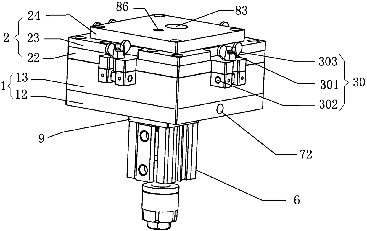
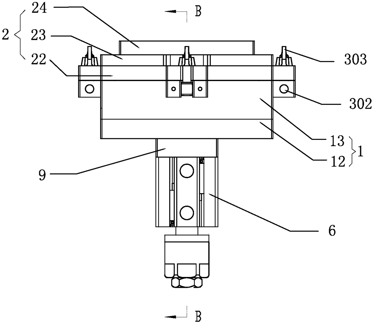
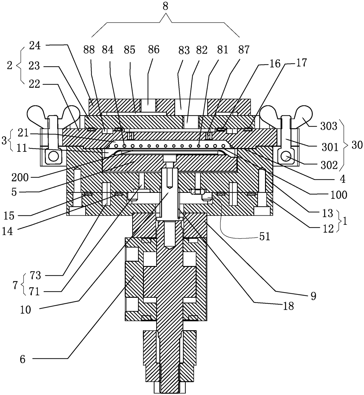
[0023] Such as Figure 1 to Figure 4 As shown, an embodiment of the present invention provides a 3D film sticking jig, which includes a base 1 with a receiving cavity 11 in the middle and a cover 2 with a molding cavity 21 in the middle. The cover 2 is correspondingly covered on the base Outside of the accommodating cavity 11 of 1, the molding cavity 21 and the accommodating cavity 11 pass through to form a filming chamber 3. Between the base 1 and the cover 2 there is also a clamping diaphragm 100 edge to position the film 100 in the filming cavi...


PUM


Abstract

An embodiment of the invention discloses a 3D film fixture comprising a base provided with a receiving cavity in the middle and a cover plate having a molding cavity in the middle thereof. The cover plate correspondingly covers the outer side of the receiving cavity of the base, the molding cavity is communicated with the receiving cavity to form a film chamber, and a clamping portion used for clamping the edge of a film to position the film in the film chamber while separating with the film to form the receiving cavity and the molding cavity is arranged between the base and the cover plate. The 3D film fixture further comprises a workpiece carrier accommodated in the receiving cavity for carrying the workpiece to be filmed, and a driving member for driving the workpiece carrier to move back and forth between the receiving cavity and the molding cavity. The driving member drives the workpiece carrier to the molding cavity, and the workpiece to be filmed on the workpiece carrier is abutted against the film, so that the film elastically deforms to be fitted to the outer surface of the workpiece to be filmed. According to the embodiment of the invention, the workpiece carrier is driven by the driving member to drive the film to be filmed to realize the automatic bonding, and the automatic filming is realized to improve the production efficiency.

Description

Technical field [0001] The invention relates to the technical field of product sticking films, in particular to a 3D sticking film jig. Background technique [0002] With the popularity of touch-screen mobile phones, film has a very considerable market. The film is also called beauty film and protective film. It is a kind of cold laminating film that can be used to mount the surface of mobile phone body, screen and other tangible objects. The film is not limited to mount mobile phones, but also can mount MP3, MP4, computer screen, mouse, Speakers and any physical objects that need to be protected. [0003] The protective film is generally applied manually. The work efficiency of the film is low, the cost is high, and the accuracy of the lamination cannot be guaranteed. Moreover, when the film is peeled from the bottom paper or tape, the manual peeling is caused by uneven force. The problem of broken diaphragms affects the effect of subsequent lamination. Furthermore, in manual re...

Claims


Application Information

Patent Timeline
Patent Type & Authority Patents(China)
IPC IPC(8): B65B33/02
CPCB65B33/02
Inventor 杨智军张邦国王毅
Owner SHENZHEN HANJIANG AUTOMATION SCI & TECH CO LTD
Learn More