
Vehicle rear protector

A rear protection and vehicle technology, which is applied to vehicle components, vehicle safety arrangements, bumpers, etc., can solve the problems of inability to ensure the passage of trucks 2a, reduce vehicle energy, and threaten the safety of cars, and achieve the effect of ensuring the passage of vehicles.

Active Publication Date: 2017-02-22
ANHUI JIANGHUAI AUTOMOBILE GRP CORP LTD
View PDF6 Cites 2 Cited by
  • Summary
  • Abstract
  • Description
  • Claims
  • Application Information

AI Technical Summary

Problems solved by technology

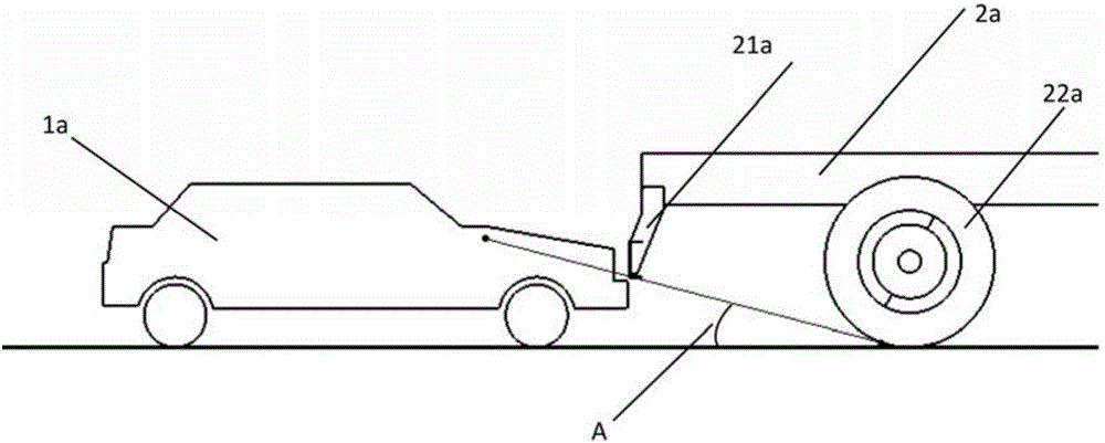
[0002] With the popularity of vehicles and the increase in the number of vehicles, the number of car accidents is also increasing. In car accidents, a considerable part of the accidents comes from rear-end collisions. Small cars often have a collapsed area at the front of the vehicle for passive safety. During the rear-end collision, the front part collapses through the front of the vehicle to reduce the energy of the vehicle during collision. However, there is a kind of rear-end collision where a car rear-ends a truck. Due to the low height of the car, the rear protection of the truck takes into account the problem of the departure angle. The rear protection of the vehicle is relatively high, and the crumple zone of the car often cannot hit the rear protection. If it is staggered with the rear protection of the truck, it may even directly hit the cab, which seriously threatens the safety of the car.
[0003] like figure 1 As shown, if the rear protection 21a of the truck 2a can just touch the front of the car 1a, the vehicle departure angle A of the truck 2a is small, and the passability of the truck 2a cannot be guaranteed
[0004] like figure 2 As shown, the vehicle departure angle A of the truck in this case is relatively large, which satisfies the passability. In the process of rear-end collision, the front part of the rear car 1a will often be staggered with the rear protection 21a, and the crumple zone of the vehicle cannot be in contact with the rear protection. impact, causing the car to be vulnerable to greater damage

Method used


Image

  • Vehicle rear protector
  • Vehicle rear protector
  • Vehicle rear protector

Examples


Embodiment Construction

[0026] In order to enable those skilled in the art to better understand the technical solutions of the present invention, the present invention will be further described in detail below in conjunction with the accompanying drawings.

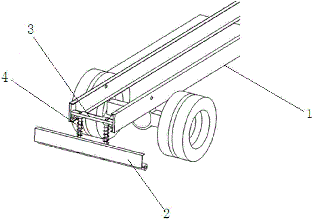
[0027] see image 3 and Figure 4 As shown, it is a vehicle rear protection provided by the embodiment of the present invention, which is installed at the rear of the longitudinal beam 7, including the rear bumper 1, which plays a role in protecting the rear of the vehicle.

[0028] A group of mounting plates 21 are horizontally extended from the rear bumper 2 toward the longitudinal beam 1. Guide holes are provided on the mounting plates 21 for guiding the installation of the guide rods so that the rear bumper 2 can move up and down along the guide holes.

[0029] The torsion bar base 3 is used to fix the torsion spring 5, and the torsion bar base 3 is horizontally arranged between two longitudinal beams 1; the side of the torsion bar base 3 fa...


PUM


Abstract

The invention discloses a vehicle rear protector which is installed at the tail portions of longitudinal beams. The vehicle rear protector comprises a rear bumper, wherein a group of installing plates horizontally extends out of the back portion of the vehicle rear protector, guiding holes are formed in the installing plates, a torsion bar base is transversely arranged between the two longitudinal beams, torsional spring fixing portions are arranged on the side, deviating from the rear bump, of the torsion bar base at intervals, the bottom of the torsion bar base faces the guiding holes and is provided with a group of guiding rods capable of vertically telescoping, the ends of the guiding rods are extending-out ends extending out of the guiding holes, and the extending-out ends are connected with the rear bump. A torsional spring is transversely arranged between the two longitudinal beams, the middle of the torsional spring is fixedly installed at a torsional spring fixing portion, and two ends of the torsional spring are respectively and fixedly connected with the longitudinal beams. Springs are installed on the torsion bar base and the guiding rods among the installing plates in a pre-tightened and sleeved mode. According to the scheme, by utilizing matching between the guiding rods and the guiding holes, it is ensured that the rear bump upwards slides along the guiding rods to ensure the trafficability when a ground clearance of the rear bump of a vehicle is small. In addition, an elastic force is provided by utilizing torsion of the torsional spring, and it is ensured that a rear-end vehicle utilizes a self structure to buffer energy.

Description

technical field [0001] The invention relates to the field of vehicle rear protection devices, in particular to a vehicle rear protection. Background technique [0002] With the popularity of vehicles and the increase in the number of vehicles, the number of car accidents is also increasing. In car accidents, a considerable part of the accidents comes from rear-end collisions. Small cars often have a collapsed area at the front of the vehicle for passive safety. During the rear-end collision, the front part collapses through the front of the vehicle to reduce the energy of the vehicle during collision. However, there is a kind of rear-end collision where a car rear-ends a truck. Due to the low height of the car, the rear protection of the truck takes into account the problem of the departure angle. The rear protection of the vehicle is relatively high, and the crumple zone of the car often cannot hit the rear protection. If it is staggered with the rear protection of the truc...

Claims


Application Information

Patent Timeline
Patent Type & Authority Applications(China)
IPC IPC(8): B60R19/56B60R19/28B60R19/38
CPCB60R19/28B60R19/38B60R19/56
Inventor 刘聪聪刘洁浩李盈盈吴昌庆刘韶雷张伟马骁宇周列新田永亮
Owner ANHUI JIANGHUAI AUTOMOBILE GRP CORP LTD
Learn More