Mechanical arm

A technology of manipulators and manipulator claws, applied in the field of robotics, can solve the problems of unilateral force, time-consuming, inaccurate opening size, etc., and achieve the effects of reduced processing amount, convenient operation and simple structure

Inactive Publication Date: 2017-02-22
上海魁殊自动化科技有限公司
View PDF14 Cites 5 Cited by
  • Summary
  • Abstract
  • Description
  • Claims
  • Application Information

AI Technical Summary

Problems solved by technology

[0002] During the processing process of the production workshop, the workpiece needs to be processed many times, which requires the workpiece to be moved between various processes, and the transfer of the workpiece by manual or general spreader has the problem of slow speed and time-consuming. Therefore, it needs a A simple manipulator structure, which can stably grab the workpiece to complete the transfer of the workpiece
In the prior art, such as CN2516324, CN103433936, CN105058354, and CN202668551 all provide a kind of manipulator, but it cannot automatically reset, unilateral force, inaccurate opening size, and complex structure.

Method used


Image

  • Mechanical arm

Examples


Embodiment Construction

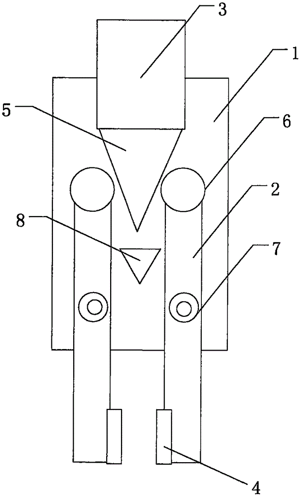
[0009] Such as figure 1 As shown, a manipulator is characterized in that it includes a base 1, a manipulator claw 2, and a push rod 3. There are two manipulator claws 2, and the middle of the manipulator claw 2 is pivotally connected to the base 1 and The two manipulator claws 2 are arranged symmetrically, and the lower end of the manipulator claw 2 has a clamping portion 4 for clamping the workpiece; the upper end of the manipulator claw 2 is in contact with one end of the push rod 3; the push rod 3 is a slender cylinder, one end of which is a conical structure 5, and the other end is connected to a power mechanism (not shown in the figure). The power mechanism adjusts the opening and closing of the manipulator claw 2 through the conical end of the push rod 3 .

[0010] Preferably, the clamping portion 4 of the manipulator claw 2 is a flat surface or a serrated surface.

[0011] Preferably, the upper end of the manipulator claw 2 is further provided with a bearing 6; the bearing...


PUM


Abstract

Provided is a mechanical arm. The mechanical arm comprises a base, mechanical grippers, a push rod and a spring-return structure; the middles of the mechanical grippers are pivoted to the base, the mechanical grippers are arranged symmetrically, and the lower ends of the mechanical grippers are each provided with a clamping part used for clamping workpieces; the upper ends of the mechanical grippers make contact with one end of the push rod; the push rod is a spindly cylinder, one end of the push rod is of a cone structure, and the other end of the push rod is connected with a power structure; the power structure performs forward action to drive the push rod so as to enable the mechanical grippers to be closed, the power structure performs reverse action, and the mechanical grippers automatically reset to loosen the workpieces under the action of torsional springs and a stop block; the reset action of the torsional springs and stopping of the stop block jointly define the sizes of openings of the mechanical grippers, and waste of stroke of the power mechanism is avoided; meanwhile, the cone structure machining allowance of the push rod is decreased, and the cost is reduced.

Description

Technical field [0001] The invention relates to the field of robots, in particular to a manipulator capable of grasping workpieces. Background technique [0002] During the processing in the production workshop, the workpiece needs to be processed multiple times, which requires the workpiece to be moved between various procedures. However, the use of manual or general spreaders for the transfer of the workpiece has the problem of slow speed and time-consuming. Therefore, a A simple manipulator structure, which can stably grasp the workpiece to complete the transfer of the workpiece. In the prior art, CN2516324, CN103433936, CN105058354, and CN202668551 all provide a manipulator, but it has the disadvantages of inability to automatically reset, unilateral force, inaccurate opening size, and complex structure. Summary of the invention [0003] Based on the above technical problems and the prior art, the present invention provides a manipulator with simple structure, convenient oper...

Claims


Application Information

Patent Timeline
IPC IPC(8): B25J15/08
CPCB25J15/08
Inventor 顾涛
Owner 上海魁殊自动化科技有限公司
Why Eureka
Try Eureka