
Car shower line drying system

A rain-drenching and car-drying technology, applied in the direction of body drying, drying, dryer, etc., can solve the problems of affecting the body inspection process, leaving a large amount of water on the body, and long distances

Active Publication Date: 2019-06-14
EFORT INTELLIGENT EQUIP CO LTD
View PDF7 Cites 0 Cited by
  • Summary
  • Abstract
  • Description
  • Claims
  • Application Information

AI Technical Summary

Problems solved by technology

[0003] In the past, the air nozzle of the drying system in the vehicle rain inspection was fixed and would not be adjusted according to the size of the vehicle body. The distance between the large-size vehicle body and the air nozzle is close, the drying effect is good, and the residual water on the body is less. It will not affect the next body inspection process; while the distance between the small-sized body and the air nozzle is far away, the drying effect is poor, and a large amount of water will remain on the body, which will affect the next body inspection process and leave a lot of water on the ground
[0004] In order to improve the drying effect of the car body in the rain detection of the whole vehicle, and solve the problem that due to the large difference in the size of the vehicle body, the fixed drying system has a good effect on drying the large-size body and poor effect on the small-size body. Adjust the distance between the air nozzle of the drying system and the body, so that the body of different sizes will not be affected by the next body inspection process after the body is dried in the rain test

Method used


Image

  • Car shower line drying system
  • Car shower line drying system
  • Car shower line drying system

Examples


Embodiment Construction

[0018] In order to make the technical means, creative features, goals and effects achieved by the present invention easy to understand, the present invention will be further elaborated below.

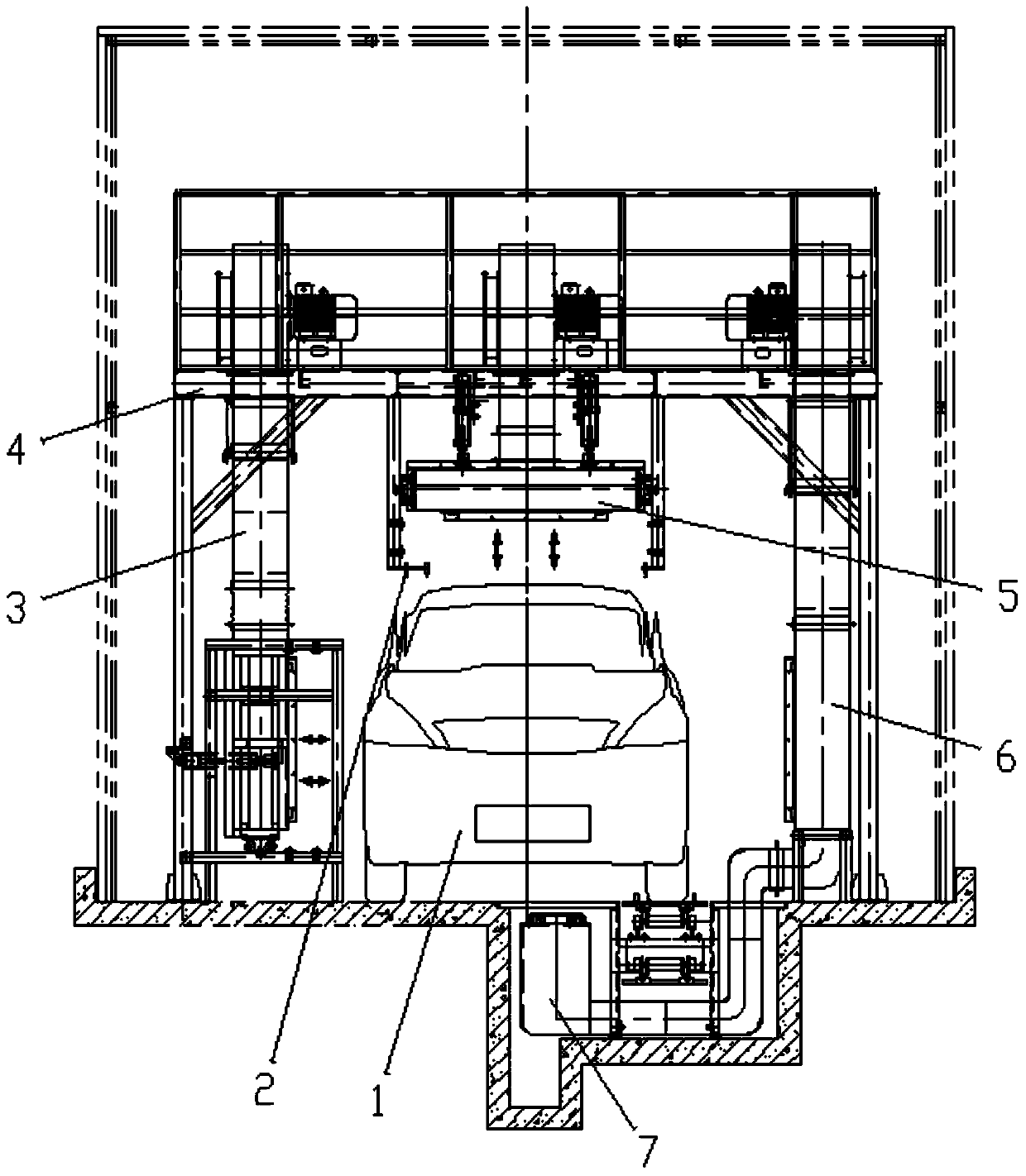
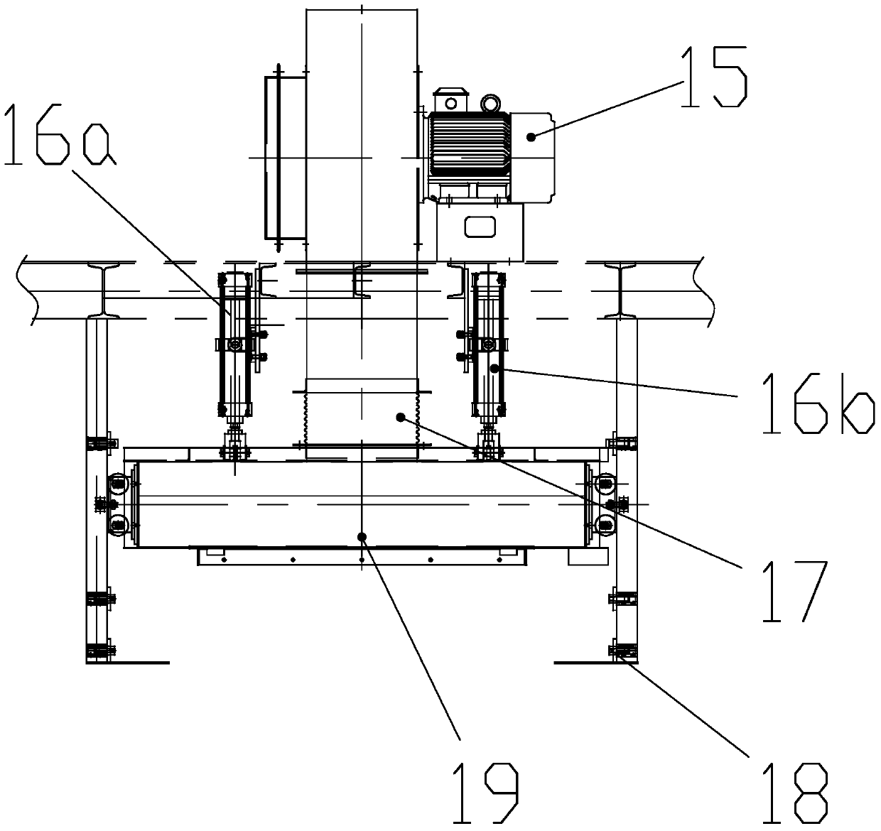
[0019] Such as Figure 1 to Figure 3 As shown, the car rain line drying system includes a fan platform 4, the right side of the lower end surface of the fan platform 4 is fixed with a fixed blowing system 6 on the right side, and the bottom of the fan platform 4 is fixed with a bottom fixed blowing system 7, so The middle part of the fan platform 4 is fixed with a top adjustable blowing system 5, and the left side of the lower end surface of the fan platform 4 is fixed with a left side adjustable blowing system 3.

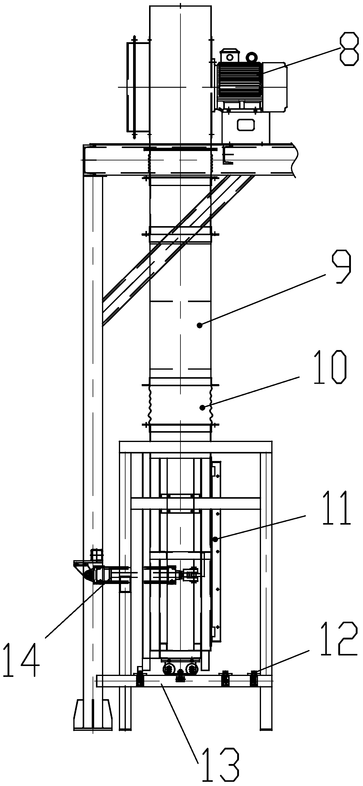
[0020] The adjustable blowing system 3 of the left side part comprises a No. 1 fan 8 fixed on the fan platform 4, the air outlet of the No. 1 fan 8 is connected with a No. 1 fixed air duct 9, and the lower end of the No. 1 fixed air duct 9 There is a side air nozzle 11 in c...


PUM


Abstract

The invention relates to an automobile rain test production line drying system. The automobile rain test production line drying system comprises a draught fan platform; a right side surface fixed air blowing system is fixed to the right side of the lower end surface of the draught fan platform; a bottom fixed air blowing system is fixed under the draught fan platform; a top adjustable air blowing system is fixed to the middle of the draught fan platform; and a left side adjustable air blowing system is fixed to the left side of the lower end surface of the draught fan platform. According to the automobile rain test production line drying system, a two-side fixing and two-side adjusting mode is adopted, and the track of an automobile is fixed to the position close to the right side surface fixed air blowing system; the automobile showering line drying system can flexibly adapt to different automobile models by adjusting the left side adjustable air blowing system and the top adjustable air blowing system; a side surface tuyere and a top tuyere are close to the automobile and dry the automobile through air cylinder adjustment, and the one-time drying effect is ensured. The model of the automobile is detected through a photoelectric sensor, thus, the model and the position of the automobile can be precisely and rapidly determined according to surface morphological differences of different automobile models, and a reference is provided for air cylinder adjustment.

Description

technical field [0001] The invention relates to the technical field of vehicle cleaning equipment, in particular to an automobile rain shower line drying system. Background technique [0002] After the vehicle is exposed to rain in the automotive industry, it is necessary to dry the water marks on the surface of the body to prevent the body from entering the next body inspection process with water marks. [0003] In the past, the air nozzle of the drying system in the vehicle rain inspection was fixed and would not be adjusted according to the size of the vehicle body. The distance between the large-size vehicle body and the air nozzle is close, the drying effect is good, and the residual water on the body is less. It will not affect the next body inspection process; while the distance between the small-sized body and the air nozzle is far away, the drying effect is poor, and a large amount of water will remain on the body, which will affect the next body inspection process ...

Claims


Application Information

Patent Timeline
Patent Type & Authority Patents(China)
IPC IPC(8): F26B21/00
CPCF26B21/003F26B21/004F26B2210/12
Inventor 黄燕吴桥周涛李启余
Owner EFORT INTELLIGENT EQUIP CO LTD
Learn More