Eureka AIR delivers breakthrough ideas for toughest innovation challenges, trusted by R&D personnel around the world.

Lateral side film sticking machine

A film laminating machine and film laminating technology, which is applied in packaging and other fields, can solve problems such as poor work efficiency, time-consuming and labor-intensive work, and low efficiency.

Inactive Publication Date: 2017-02-15
SHENZHEN DEWEI PRECISION MOLD
View PDF6 Cites 11 Cited by
  • Summary
  • Abstract
  • Description
  • Claims
  • Application Information

AI Technical Summary

Problems solved by technology

[0004] The object of the present invention is to aim at the defects of the above-mentioned prior art, to provide a side film laminating machine, which overcomes the poor adaptability, slow speed, low efficiency, time-consuming and labor-intensive work efficiency existing in the prior art. Defects

Method used

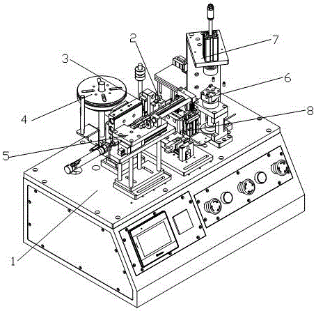
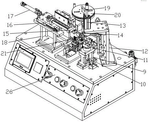
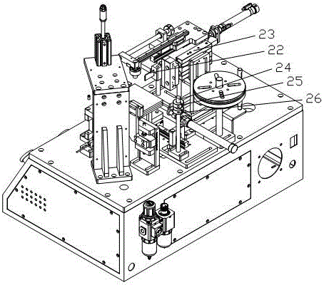

Image

  • Lateral side film sticking machine
  • Lateral side film sticking machine
  • Lateral side film sticking machine

Examples


Embodiment Construction

[0025] The following will clearly and completely describe the technical solutions in the embodiments of the present invention with reference to the accompanying drawings in the embodiments of the present invention. Obviously, the described embodiments are only some, not all, embodiments of the present invention. Based on the embodiments of the present invention, all other embodiments obtained by persons of ordinary skill in the art without creative work, any modifications, equivalent replacements, improvements, etc., shall be included in the protection scope of the present invention Inside.

[0026] Such as figure 1 , 2 , 3, the side film laminating machine of the present invention includes a frame 1, a feeding module 2 arranged on the frame 1, a film cutting module 3, a roll module 4, a film pressing module 5, a rotary mold Group 6, compression module 7 and clamping device 8;

[0027] The rotating module 6 includes a rotating support frame 9 and a rotatable rotating shaft ...


PUM


Abstract

The invention discloses a lateral side film sticking machine, which comprises a feeding module, a film cutting module, a material coil module, a film laminating module, a rotating module, a pressing module and a film clamping device; the rotating module comprises a rotating shaft and a positioning jig; the pressing module comprises a pressing down cylinder for pressing a product to be subjected to film sticking, the center of the pressing down cylinder and that of the rotating shaft are concentric, the film laminating module comprises a film pressing roller, a film pressing block, a moving lateral plate for supporting the film pressing roller and the film pressing block as well as a lateral film pressing cylinder and a lateral film pressing support frame acting on the moving lateral plate; the material coil module comprises a material coil support frame and a rotatable film disc arranged on the material coil support frame and used for placing a film material; the feeding module comprises a feeder enabling the film material to advance; the film clamping device comprises a clip, a clip cylinder enabling the clip to act and a clip height controlling cylinder for controlling a height of the clip; and the film cutting module comprises a cutter and a film cutting cylinder for controlling the cutter to act. The lateral side film sticking machine according to the machine is specific to film sticking of products with lateral sides being high shiny sides.

Description

technical field [0001] The invention relates to the technical field of side film sticking equipment for electronic products, in particular to a side film sticking machine. Background technique [0002] The side film sticking equipment is a film sticking equipment for all electronic products with high glossy sides. The purpose is to ensure that the product will not be damaged during the next process and turnover, and improve the yield rate of the product. [0003] But the adaptability of the side film sticking equipment of prior art is bad, and speed is slow, and efficient is low, wastes time and effort, and work efficiency is poor. Contents of the invention [0004] The object of the present invention is to aim at the defects of the above-mentioned prior art, to provide a side film laminating machine, which overcomes the poor adaptability, slow speed, low efficiency, time-consuming and labor-intensive work efficiency existing in the prior art. Defects. [0005] In order ...

Claims


Application Information

Patent Timeline
Patent Type & Authority Applications(China)
IPC IPC(8): B65B33/02
CPCB65B33/02
Inventor 刘占飞雷国平牛武
Owner SHENZHEN DEWEI PRECISION MOLD
Why Eureka
Eureka Blog
Learn More