
Distributed power station

A distributed and power station technology, applied in the direction of photovoltaic power generation, electrical components, photovoltaic modules, etc., can solve problems such as heavy roof load and safety hazards

Inactive Publication Date: 2017-02-08
晶科电力科技股份有限公司
View PDF5 Cites 0 Cited by
  • Summary
  • Abstract
  • Description
  • Claims
  • Application Information

AI Technical Summary

Problems solved by technology

Even if pier is made on the top of the roof, it can effectively avoid damage to the roof, but after long-term use, it is easy to cause the roof to bear too much weight and cause safety hazards

Method used


Image

  • Distributed power station
  • Distributed power station

Examples


Embodiment Construction

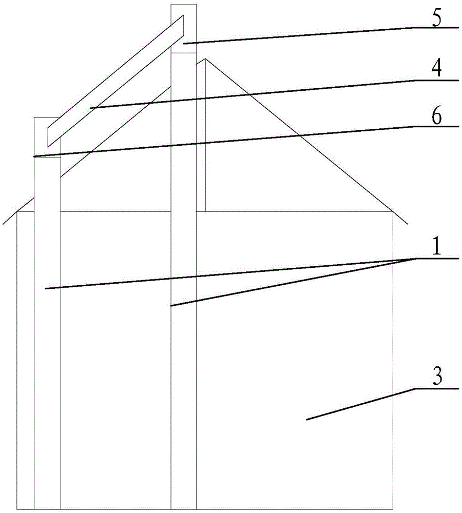
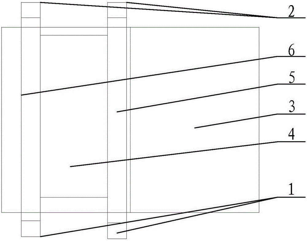
[0024] The embodiment of the invention discloses a distributed power station to effectively solve the problem of security threats to the house of the distributed power station.

[0025] The following will clearly and completely describe the technical solutions in the embodiments of the present invention with reference to the accompanying drawings in the embodiments of the present invention. Obviously, the described embodiments are only some, not all, embodiments of the present invention. Based on the embodiments of the present invention, all other embodiments obtained by persons of ordinary skill in the art without making creative efforts belong to the protection scope of the present invention.

[0026] see Figure 1-Figure 2 , figure 1 A schematic diagram of the side view structure of the distributed power station provided by the embodiment of the present invention; figure 2 It is a schematic top view structural diagram of a distributed power station provided by an embodim...


PUM


Abstract

The invention discloses a distributed power station. The distributed power station comprises a house body and a photovoltaic assembly. The distributed power station is characterized by comprising a first support device, a second support device and an installation seat for installing the photovoltaic assembly; the bottom ends of the first support device and the second support device are abutted against the ground; the first support device and the second support device are arranged on the left side and the right side of the house body; the installation seat is arranged on the upper side of a roof of the house body, and the left end and the right end of the installation seat are fixedly connected to the first support device and the second support device; on the distributed power station, because the first support device and the second support device are arranged on the left side and the right side of the house body, the load bearing of the roof can be effectively reduced through the support of the first support device and the second support device and the safety of the house body can be guaranteed. Meanwhile, the front side and the back side of the house body can be effectively avoided and lighting inside the house body can be ensured. As a result, the distributed power station can effectively solve the safety threatening problem of the distributed power station house body in the prior art.

Description

technical field [0001] The present invention relates to the technical field of power generation, more specifically, to a distributed power station Background technique [0002] At present, common distributed power stations mainly use photovoltaic modules to generate electricity, and photovoltaic modules can convert solar energy into electrical energy. In order to be more intuitive to use, in the prior art, photovoltaic modules are often arranged on the roof to form a distributed power station. [0003] In order to facilitate the fixing of photovoltaic modules, in the prior art, expansion screws are often placed on the roof to install and fix the photovoltaic modules. However, after long-term research by the inventor, it has been found that after the expansion screws are set, it is easy to cause cracks in the roof, and then it is easy to cause water leakage. Even if pier is performed on the top of the roof, although this can effectively avoid damage to the roof, after long-...

Claims


Application Information

Patent Timeline
Patent Type & Authority Applications(China)
IPC IPC(8): H02S20/23
CPCH02S20/23Y02B10/10Y02E10/50
Inventor 江庆彪刘德元刘亚锋金浩戴健李娜蔡后敏
Owner 晶科电力科技股份有限公司
Learn More