
Missile-borne floating air ball system

A balloon and bomb-borne technology, which is applied to balloon vehicles and other directions, can solve problems such as application limitations and aerostats are vulnerable to attack, achieve good practical value, and be beneficial to military and emergency applications.

Active Publication Date: 2017-02-08
BEIJING RES INST OF SPATIAL MECHANICAL & ELECTRICAL TECH
View PDF5 Cites 9 Cited by
  • Summary
  • Abstract
  • Description
  • Claims
  • Application Information

AI Technical Summary

Problems solved by technology

[0002] Traditional aerostats are generally released on the ground, but when the aerostat is used for military purposes, this method of release is difficult to implement in the enemy's position. If it is released in the own position, the aerostat will enter the enemy's airspace The process is extremely vulnerable to attack, so its application will be greatly limited
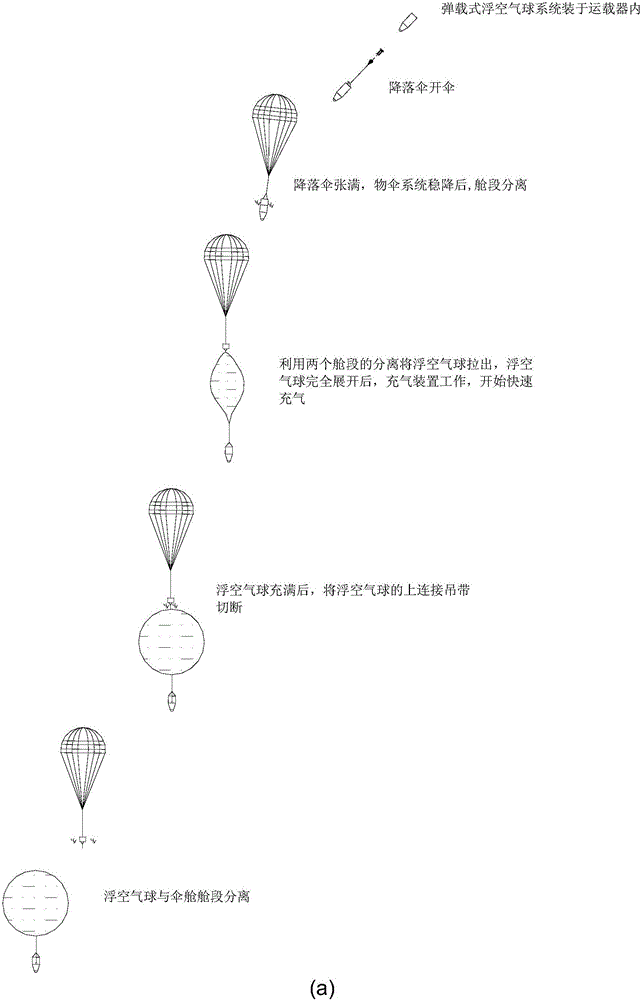
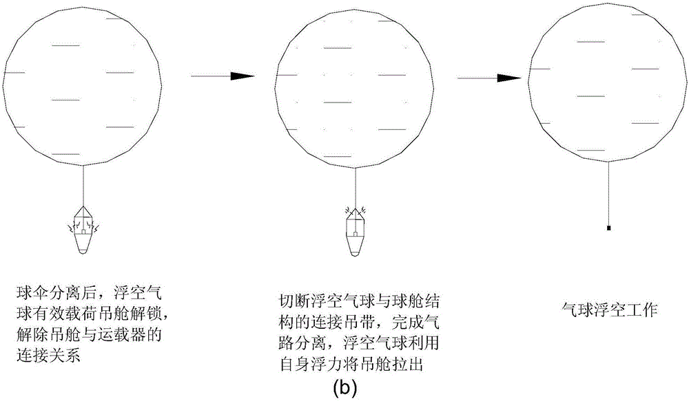
The missile-borne floating air balloon system is to launch the folded and packaged floating air balloon to a predetermined area by means of carrier rockets or missiles. After the floating air balloon is separated from the carrier, it is pulled out in the air, unfolded, and inflated. The payload starts to work. Since the balloon can carry multiple loads such as investigation, communication, and environmental detection, it has high practical value in actual combat and emergency environments. At present, there are no similar products at home and abroad.

Method used


Image

  • Missile-borne floating air ball system
  • Missile-borne floating air ball system
  • Missile-borne floating air ball system

Examples


Embodiment Construction

[0025] Aiming at the deficiencies of the prior art, the present invention proposes a missile-borne floating air balloon system, which solves the problem of rapid deployment of floating air balloons in battlefield environments and emergency conditions, and changes the bottom-up deployment method of traditional floating air balloons , using the carrier to realize automatic deployment on the battlefield from top to bottom, it is especially suitable for special purposes such as investigation, early warning, and earth observation. The present invention will be described in detail below in conjunction with the accompanying drawings.

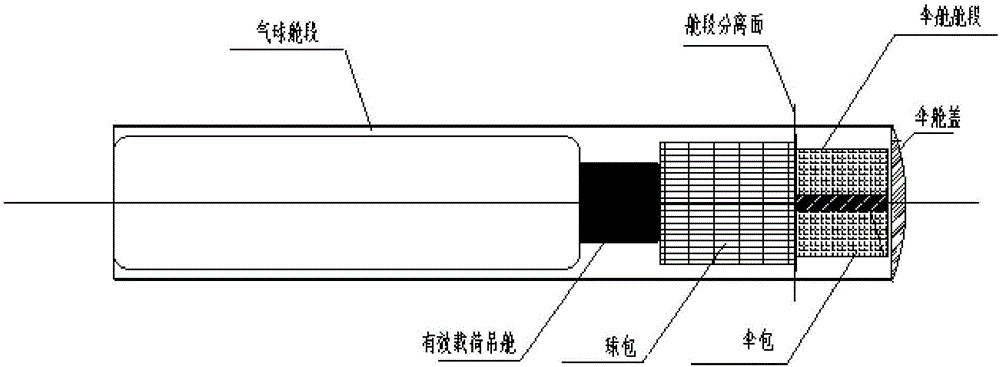
[0026] A bomb-loaded floating air balloon system of the present invention includes an umbrella cabin structure, a parachute, a floating air balloon, a catapult, a separation nut, a ball umbrella separation cutter, a ball cabin separation cutter, a pipeline separation device, an inflation device, and a ball cabin Cabin section, umbrella cabin section.

...


PUM


Abstract

The invention provides a missile-borne floating air ball system. The system comprises a parachute, a floating air ball, a catapult cylinder, separation nuts, a ball and parachute separating cutter, a ball cabin separating cutter, a pipeline separating device, an inflating device, a ball cabin, a parachute cabin and an effective load, wherein after a destination area is reached, the catapult cylinder catapults a parachute pack and the parachute is opened, a floating air ball pack is pulled out of the ball cabin by utilizing separation of the parachute cabin and the ball cabin, the floating air ball is inflated by the inflating device, then the pipeline separating device separates an inflating pipeline from the floating air ball, the ball and parachute separating cutter separates the floating air ball from the parachute cabin, an effective load pod is separated from a vehicle, the ball cabin separating cutter separates the floating air ball from the ball cabin, the effective load pod is pulled out of the ball cabin, and the floating air ball drives the effective load to work in the air. Compared with existing floating air balls released on the ground, the system has the effects of changing the traditional mode of releasing the floating air balls from bottom to top and achieving automatic release from top to bottom and is more beneficial to military and emergency application.

Description

technical field [0001] The invention relates to a floating air balloon, in particular to a bomb-borne floating air balloon system, which can be packed in a vehicle such as a launch vehicle or a missile, and is pulled out from the interior of the vehicle after the vehicle flies to a predetermined area, unfolded, Inflates and finally floats. Background technique [0002] Traditional aerostats are generally released on the ground, but when the aerostat is used for military purposes, this method of release is difficult to implement in the enemy's position. If it is released in the own position, the aerostat will enter the enemy's airspace The process is extremely vulnerable to attack, so its application will be greatly limited. The missile-borne floating air balloon system is to launch the folded and packaged floating air balloon to a predetermined area by means of carrier rockets or missiles. After the floating air balloon is separated from the carrier, it is pulled out in the...

Claims


Application Information

Patent Timeline
IPC IPC(8): B64B1/40
CPCB64B1/40
Inventor 曹旭廖航武士轻唐明章黎光宇刘海烨徐诚方刘兴华王文涛贾子年韩言勋
Owner BEIJING RES INST OF SPATIAL MECHANICAL & ELECTRICAL TECH
Learn More