Fiber paste spraying and conveying device

A technology for conveying device and fiber paste, which is applied in the direction of spraying device, device for coating liquid on the surface, coating, etc., which can solve the problems of large floor area, fiber paste coating, electrical insulation short circuit, etc., and reduce the replacement of fiber The number of paste hoppers, avoiding the accumulation of fiber paste, and preventing the effect of valve blockage

Inactive Publication Date: 2017-02-08
SHANDONG PACIF OPTICS FIBER & CABLE CO LTD
View PDF6 Cites 6 Cited by
  • Summary
  • Abstract
  • Description
  • Claims
  • Application Information

AI Technical Summary

Problems solved by technology

[0002] In the optical cable industry, according to the process requirements, fiber paste should be coated on the steel core, optical cable core, and steel / aluminum strip. The equipment currently used in the industry, the steel core, optical cable core, and steel / aluminum strip coating fiber paste system are respectively Independent work, not related to each other, can not make reasonable comprehensive use of related equipment; the fiber paste supply system of the existing coating equipment pumps the fiber paste in the original packaging barrel into another transitional fiber paste barrel, and then passes through the fiber paste pump Pour the fiber paste into the equipment for coating the fiber paste; when the fiber paste is poured into the transition fiber paste barrel, the fiber paste often appears to be smeared; and the current fiber paste spraying machine often puts the fiber paste in the process of spraying the fiber paste The fiber paste is sprayed out from the equipment, making it difficult to clean the factory environment, and the insulation of electrical appliances is damaged, resulting in short circuits, etc.
[0003] It can be seen that the current method of coating fiber paste separately and using the transitional fiber paste barrel to add fiber paste makes the spraying fiber paste equipment occupy a large area, which cannot make reasonable use of the factory space; the fiber paste spraying machine transfers the fiber paste oil mist from the equipment Sanitation and equipment failures caused by internal flying will increase the production cost and capital investment of the enterprise

Method used


Image

  • Fiber paste spraying and conveying device
  • Fiber paste spraying and conveying device
  • Fiber paste spraying and conveying device

Examples


Embodiment Construction

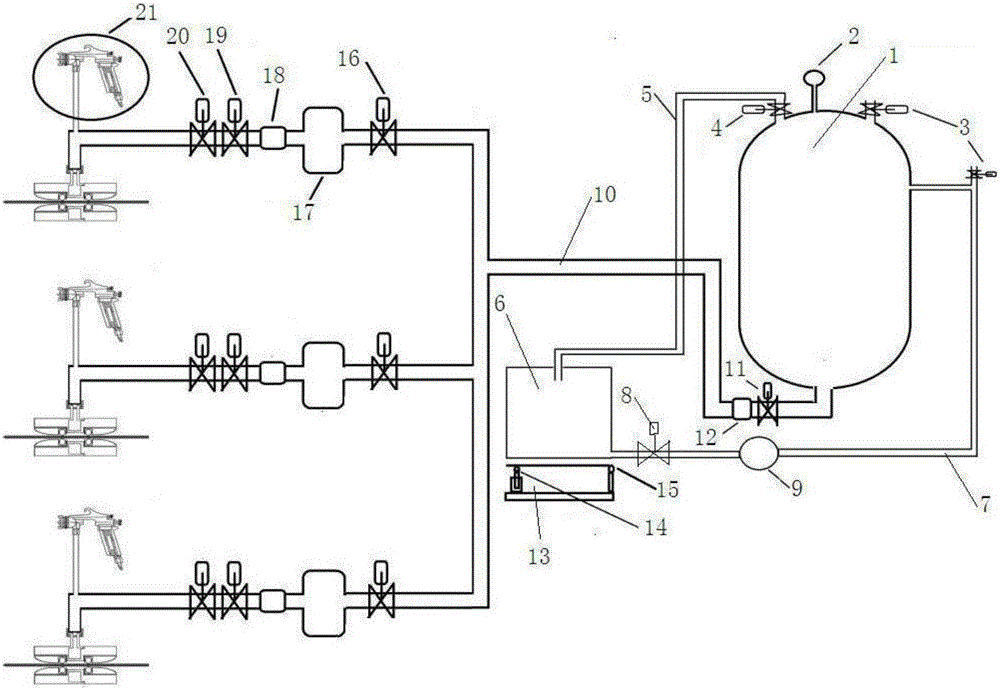
[0025] As shown in the figure, a fiber paste spraying and conveying device of the present invention includes a fiber paste conveying part and a fiber paste spraying part; it is characterized in that:

[0026] The fiber paste conveying part is as follows: a pressure gauge and a first controller 2 are connected to the upper part of the fiber paste pressure tank 1, and an exhaust valve 3 is connected to the tank body on one side of the pressure gauge to discharge the gas in the tank; An overpressure relief valve 4 is installed on the upper part of the tank body on the other side, and is connected with a first pipeline 5. The other end of the first pipeline is connected to the top of the fiber paste barrel. When the fiber paste pressure in the tank is greater than the set pressure, the overflow The flow valve is opened, and the fiber paste is guided into the fiber paste bucket by the pipeline; the second pipeline 7 is also connected to the tank body of the fiber paste pressure tank...


PUM


Abstract

The invention discloses a fiber paste spraying and conveying device. The fiber paste spraying and conveying device comprises a fiber paste conveying part and a fiber paste spraying part. According to the fiber paste conveying part, a pressure gage and a first controller are connected to the upper portion of a fiber paste pressure tank; an exhaust valve is connected to the part, on one side of the pressure gage, of a tank body; an overpressure overflow valve is installed on the upper portion of the other side of the tank body and is connected with a first pipeline; the other end of the first pipeline is connected to the top of a fiber paste bucket; a second pipeline is further connected to the tank body of the fiber paste pressure tank and is connected to the bottom of the fiber paste bucket; and a third pipeline is connected to the bottom of the fiber paste pressure tank and is connected with the fiber paste spraying part. According to the fiber paste spraying part, the third pipeline is in parallel connection with two or more spraying pipelines and then connected with a spraying box. According to the fiber paste spraying and conveying device, the purposes that during spraying of a steel core, an optical cable core and a steel/aluminum strip, fiber paste conveying equipment is shared, and fiber paste oil mist is prevented from flying out of the equipment during fiber paste spraying are achieved.

Description

technical field [0001] The invention belongs to the field of optical cable production equipment, in particular to a fiber paste spraying and conveying device. Background technique [0002] In the optical cable industry, fiber paste should be coated on steel cores, optical cable cores, and steel / aluminum strips according to process requirements. The current equipment used in the industry, steel cores, optical cable cores, and steel / aluminum strips are coated with fiber paste systems. Independent work, not related to each other, can not make reasonable comprehensive use of related equipment; the fiber paste supply system of the existing coating equipment pumps the fiber paste in the original packaging barrel into another transitional fiber paste barrel, and then passes through the fiber paste pump Pour the fiber paste into the equipment for coating the fiber paste; when the fiber paste is poured into the transition fiber paste barrel, the fiber paste often appears to be smeare...

Claims


Application Information

Patent Timeline
Patent Type & Authority Applications(China)
IPC IPC(8): B05B15/12B05B13/00B05B12/00B05B15/04G02B6/44
CPCB05B12/008B05B13/00B05B14/00B05B14/40B05B16/00G02B6/4479Y02P70/10
Inventor 王永恒杜存斌郭亚亭李冠魁高宪武
Owner SHANDONG PACIF OPTICS FIBER & CABLE CO LTD
Why Eureka
Try Eureka