Portable switch cabinet handcart rail

A cabinet handcart and portable technology, applied in the direction of pull-out switch cabinets, switchgear, electrical components, etc., can solve the problems of high energy consumption, no guiding function, and reduced work efficiency, so as to improve smoothness and eliminate frustration , the effect of improving work efficiency

Inactive Publication Date: 2017-02-01
STATE GRID SHANDONG ELECTRIC POWER COMPANY WEIFANG POWER SUPPLY +1
View PDF6 Cites 4 Cited by
  • Summary
  • Abstract
  • Description
  • Claims
  • Application Information

AI Technical Summary

Problems solved by technology

Although this kind of switchgear has obvious advantages at present, there are also disadvantages that cannot be ignored. For example: 1. During the switching operation, it is necessary to frequently pull out and push the handcart of the switchgear. It consumes a lot of physical strength; 2. The height of the traditional handcart switch is about 10~20cm from the ground. When the handlebar switch is pulled out and pushed into the switch cabinet, the track needs to be used, but the traditional track rarely has a technical design. There is a slope between the iron plate on the switch cabinet and the ground, so as to complete the work of pulling out and pushing the handcart switch; 3. Since the traditional track of the switch cabinet has no guiding function, it is very difficult for the staff to push and pull out every time. 2-3 people grasp the direction and drag it hard. Sometimes because the position of the track moves or the direction is wrong, the staff need to push repeatedly for 3 or 4 times, which greatly reduces the work efficiency; 4. Because the traditional track of the switch cabinet is only a hard The iron plate does not have the function of width adjustment, so each switch cabinet must be equipped with a track suitable for its own size, which not only causes waste, but also must find the correct track to operate when switching, which is very cumbersome and huge Affected work enthusiasm and efficiency

Method used


Image

  • Portable switch cabinet handcart rail
  • Portable switch cabinet handcart rail

Examples


Embodiment Construction

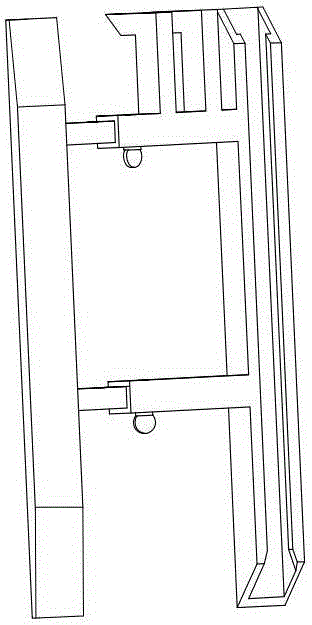
[0015] As shown in the figure, the handcart track of the portable switch cabinet includes longitudinal rails 1 arranged in parallel on the left and right, and the two longitudinal rails are fixed together through a width adjustment device. The front end of the width adjustment device is fixed with a card arm 2 extending toward the switch cabinet. The bottom of the card arm is fixed with a claw 3 that is hooked with the slot at the bottom of the switch cabinet. At least one longitudinal rail is fixed with an upwardly extending limit plate 4 on both sides, and the upper end of the limit plate is fixed with a guide plate that extends toward each other. 5. There is a gap 6 between the two guide plates to match the wheel of the switch cabinet handcart, and the entrance of the gap is set as a bell mouth 7 with a wide outer end and a narrow inner end.

[0016]The handcart track of the portable switch cabinet mainly includes two longitudinal rails arranged in parallel and a width adjus...


PUM


Abstract

The invention discloses a portable switch cabinet handcart rail. The portable switch cabinet handcart rail comprises longitudinal rails, wherein the longitudinal rails are arranged in parallel in a left-right way and are fixedly connected by a width adjustment device, clamping arms are fixedly arranged at a front end of the width adjustment device and extend towards a switch cabinet, clamping claws are fixedly arranged at the bottoms of the clamping arms and are matched with clamping groove hooks at the bottom of the switch cabinet, limiting plates are arranged at two sides of at least one longitudinal rail and upwards extend, two guide plates are fixedly arranged at the upper end of the limiting plate and extend opposite to each other, a gap is formed between the two guide plates and is matched with switch cabinet handcart wheels, and an inlet end of each gap is arranged to be a bell mouth with a wide external end and a narrow internal end. The portable switch cabinet handcart rail has the advantages that the portable switch cabinet handcart rail is reliably connected with a switch cabinet and is not liable to swing, a handcar can be rapidly and accurately aligned to an entrance of the switch cabinet, the alignment ratio is improved, the handcar is prevented from being pulled and pushed repeatedly, different switch cabinet widths can be adapted by adjusting the width of the handcart rail, the handcar can be successfully pushed to the switch cabinet in one time, switching operation can be completed by a person, and the operation efficiency can be greatly improved; and moreover, the portable switch cabinet handcart rail is small in size, is convenient to carry and occupies small space for placing.

Description

technical field [0001] The invention relates to a handcart track of a portable switch cabinet. Background technique [0002] In the control system of the power system, in order to ensure the safety and reliability of the switch control operation, the power switch cabinet is generally designed to have a structure with a trolley inside the cabinet. In this way, when the switch control operation is performed, the operation can be completed only by pulling out and pushing the trolley, which is very simple. The switch control operation is carried out by pushing and pulling the trolley, which can not only avoid possible electric shock accidents caused by the operator’s close contact with the exposed point of the switch, but also the pulled trolley also plays an isolation role, which greatly improves the operating safety. Although this kind of switchgear has obvious advantages at present, there are also disadvantages that cannot be ignored. For example: 1. During the switching ope...

Claims


Application Information

Patent Timeline
IPC IPC(8): H02B11/127
Inventor 刘小欧王冰张军高金伟孙明星赵中亮陈岩高振国吴杰谢震
Owner STATE GRID SHANDONG ELECTRIC POWER COMPANY WEIFANG POWER SUPPLY
Why Eureka
Try Eureka