Connection piece in modular wall panel
An adapter and modular technology, which is applied to the parts, connections, electrical components and other directions of the connecting device, can solve the problems such as the inability to mass-produce circuit boards, existing problems, and increased production and manufacturing costs.
- Summary
- Abstract
- Description
- Claims
- Application Information
AI Technical Summary
Problems solved by technology
Method used
Image
Examples
Embodiment 1
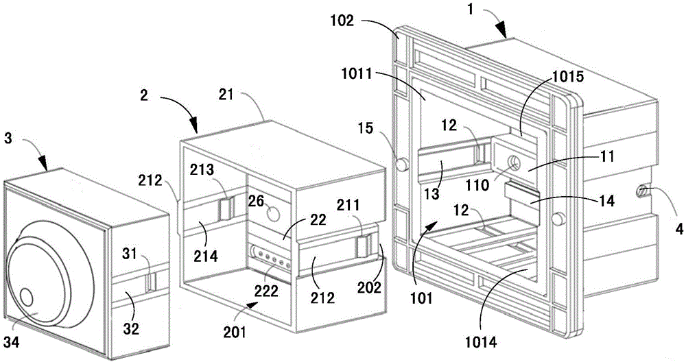
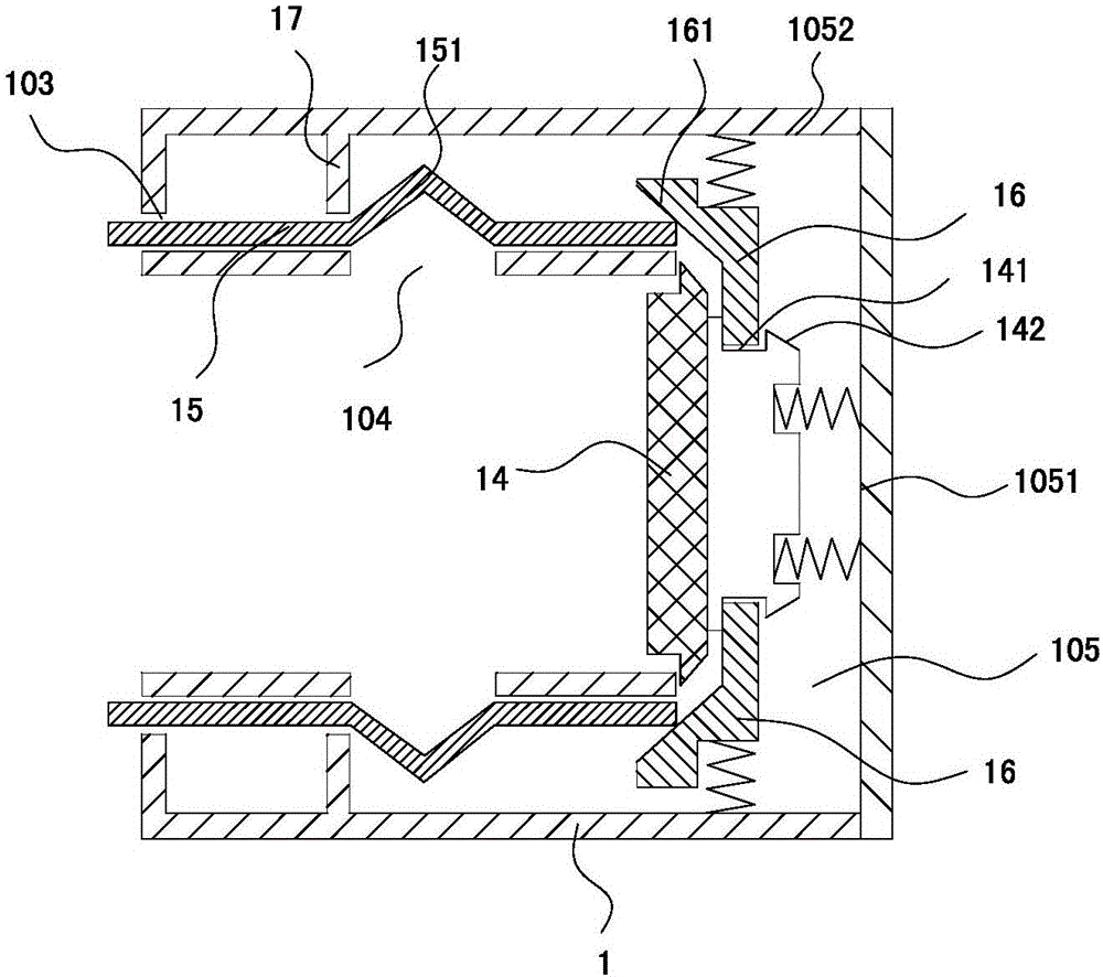
[0033] refer to figure 1 , this embodiment is a wall panel device, usually installed on the wall of the room, the whole wall panel device generally includes a base 1 and a functional module installed on the base 1, the base 1 in this embodiment It is embedded in the wall. The base 1 is provided with a power-taking terminal 11 connected to the power bus 4. The power bus 4 referred to here can be a power supply line for power supply or a signal for data transmission. The circuit can also be a combination of the two. In this embodiment, as preferred, the power bus 4 is a combination of the two, that is, it includes a power supply circuit for power supply and a signal circuit for data transmission. The power-taking terminal 11 is connected to the power bus. 4 connected, so the power-taking terminal 11 also has the function of power supply and data transmission correspondingly. The functional modules are electrically coupled to the power-taking terminal 11 , that is, the functiona...
Embodiment 2
[0068] The difference between this embodiment and Embodiment 1 is:
[0069] Such as Figure 5 As shown, the adapter housing 21 in this embodiment is not a box-shaped housing, but a plate-shaped housing, and the control circuit board 22 is still installed on the adapter housing 21, and is electrically coupled with the power-taking terminal 11 Since the structure of the adapter housing 21 changes, the plug-in module 3 in this embodiment is directly detachably connected to the base 1 without passing through the adapter housing 21, but the plug-in module 3 and the control circuit board 22 are still electrically coupled through the electrical coupling connection mechanism in the first embodiment.
[0070] In this embodiment, the connection between the plug-in module 3 and the base 1 is realized through a fourth detachable connection mechanism. The fourth detachable connection mechanism includes a fourth rib 37 arranged on the plug-in module 3, and a The fourth buckle groove 18 on...
Embodiment 3
[0075] Such as Image 6 As shown, this embodiment is optimized and improved on the basis of Embodiment 2. The difference between this embodiment and Embodiment 2 is that firstly, the plug-in module 3 in this embodiment is a single audio module, and the audio module in this embodiment The module is a sound, and the sound is provided with a sound switch 3031. In addition, the key point is that the driving assembly in this embodiment also includes two push rods 19. The method is the same as that of the ejector block 14, and the pusher block 16 is also resisted by the movable rod 15, and then the pusher block 16 pushes the ejector rod 19 out. Image 6 Due to the viewing angle problem, the ejector pins 19 located at the upper two corners are not shown.
[0076] At the same time, an avoidance groove 25 for avoiding the push rod 19 is provided at the corner of the adapter housing 21, that is, the push rod 19 directly interacts with the plug-in module 3 through the avoidance groove 2...
PUM
 Abstract
Description
Claims
Application Information
 - R&D Engineer
- R&D Manager
- IP Professional
- Industry Leading Data Capabilities
- Powerful AI technology
- Patent DNA Extraction
Browse by: Latest US Patents, China's latest patents, Technical Efficacy Thesaurus, Application Domain, Technology Topic, Popular Technical Reports.
© 2024 PatSnap. All rights reserved.Legal|Privacy policy|Modern Slavery Act Transparency Statement|Sitemap|About US| Contact US: help@patsnap.com


