
Plastic extruding machine

An extruder and plastic technology, applied in the field of plastic processing, can solve the problems of low extruder working efficiency, reduce material discharge speed, material feeding lag, etc., so as to eliminate material feeding lag, ensure processing speed and sealing performance. Good results

Inactive Publication Date: 2017-02-01
ZHENGZHOU ZHENGXIAN PHARMA CO LTD
View PDF4 Cites 3 Cited by
  • Summary
  • Abstract
  • Description
  • Claims
  • Application Information

AI Technical Summary

Problems solved by technology

[0002] In the process of plastic processing, it is necessary to use an extruder to squeeze the plastic into the mold. The extruder relies on the pressure and shear force generated by the rotation of the screw, which can fully plasticize and mix the material, and then shape it through the die. , but the working efficiency of the traditional extruder is low, and the speed of the screw is lower than the preset speed due to the accumulation of raw materials at the discharge port
[0003] In order to solve the above problems, the existing patent announcement number is CN105881867A patent has announced a kind of extruder, but this kind of device has disadvantages in the process of implementation, which causes the material to be delivered with hysteresis. In the second extrusion chamber, after the operation of the first extrusion chamber is completed, the material in the second extrusion chamber needs to be squeezed into the first extrusion chamber before the second extrusion can be carried out, so that there will be more in the middle A procedure, which in turn reduces the output speed

Method used


Image

  • Plastic extruding machine

Examples


Embodiment Construction

[0014] The following will clearly and completely describe the technical solutions in the embodiments of the present invention with reference to the accompanying drawings in the embodiments of the present invention. Obviously, the described embodiments are only some, not all, embodiments of the present invention. Based on the embodiments of the present invention, all other embodiments obtained by persons of ordinary skill in the art without making creative efforts belong to the protection scope of the present invention.

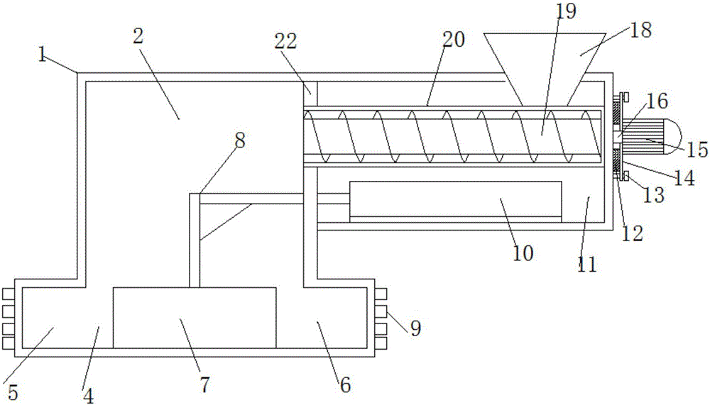
[0015] see figure 1 , in an embodiment of the present invention, a plastic extruder includes a processing box 1, a buffer cavity 2 and an installation cavity 11. The processing box 1 is composed of a buffer cavity 2 and an installation cavity 11. A partition 22 is arranged between them, and a transmission cylinder 20 is arranged horizontally in the installation cavity 11, and the left end of the transmission cylinder 20 passes through the partition 22. The ri...


PUM


Abstract

The invention discloses a plastic extruding machine. The plastic extruding machine comprises a processing box, a cache cavity and an installation cavity, wherein the processing box is composed of the cache cavity and the installation cavity, a partition is arranged between the installation cavity and the cache cavity, a transmission drum is horizontally arranged in the installation cavity, the left end of the transmission drum passes through the partition, a transmission rod is arranged in the transmission drum, a driving shaft is arranged on the right end of the transmission rod, the right end of the driving shaft passes through the right side wall of the processing box and is connected with a driving motor, a motor base is arranged on the outer side of the driving motor, a gasket is arranged between the motor base and the processing box, a feed hopper is arranged on the right upper end of the processing box, the lower end opening of the feed hopper communicates with the transmission drum, an aggregate cavity is formed in the lower end of the cache cavity, an extruding cavity I and an extruding cavity II are respectively formed in both sides of the aggregate cavity, and the bottoms of the extruding cavity I and the extruding cavity II are flush with the bottom of the aggregate cavity. The plastic extruding machine has the advantages of simple and reasonable structure, good sealing performance and high practicability, the problem of hysteresis of material transmission of an existing device is solved, and the processing speed of the device is guaranteed.

Description

technical field [0001] The invention relates to the technical field of plastic processing, in particular to a plastic extruder. Background technique [0002] In the process of plastic processing, it is necessary to use an extruder to squeeze the plastic into the mold. The extruder relies on the pressure and shear force generated by the rotation of the screw, which can fully plasticize and mix the material, and then shape it through the die. , but the traditional extruder has low working efficiency. Due to the accumulation of raw materials at the discharge port, the speed of the screw is lower than the preset speed. [0003] In order to solve the above problems, the existing patent announcement number is CN105881867A patent has announced a kind of extruder, but this kind of device has disadvantages in the process of implementation, which causes the material to be delivered with hysteresis. In the second extrusion chamber, after the operation of the first extrusion chamber is...

Claims


Application Information

Patent Timeline
Patent Type & Authority Applications(China)
IPC IPC(8): B29C47/54B29C47/36
CPCB29C48/388B29C48/475
Inventor 顾晓荣
Owner ZHENGZHOU ZHENGXIAN PHARMA CO LTD
Learn More