
Piezoelectric ceramic fiber power generation system, power generation shoes and power generation tire

A technology of piezoelectric ceramics and power generation systems, which is applied in the direction of generators/motors, piezoelectric effect/electrostrictive or magnetostrictive motors, tire parts, etc., and can solve problems such as inability to collect automatically

Active Publication Date: 2017-01-25
盐城宇欣陶瓷科技有限公司
View PDF9 Cites 4 Cited by
  • Summary
  • Abstract
  • Description
  • Claims
  • Application Information

AI Technical Summary

Problems solved by technology

[0004] The purpose of the present invention is to provide a piezoelectric ceramic fiber power generation system, power generation shoes and power generation tires, which aims to solve the technical problem that existing shoes or tires or other moving parts cannot automatically collect and use the mechanical energy generated by themselves to generate power

Method used


Image

  • Piezoelectric ceramic fiber power generation system, power generation shoes and power generation tire
  • Piezoelectric ceramic fiber power generation system, power generation shoes and power generation tire
  • Piezoelectric ceramic fiber power generation system, power generation shoes and power generation tire

Examples


no. 1 example

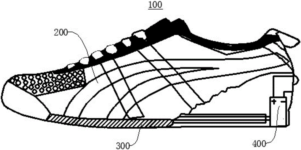
[0036] figure 1 For the structural schematic diagram of the power generation shoes provided by the first embodiment of the present invention, please refer to figure 1 .

[0037]The power generation shoe 100 provided in this embodiment includes a shoe upper 200 , a shoe sole 300 and a piezoelectric ceramic fiber power generation system 400 . The sole 300 is hollow and made of artificial rubber. The piezoelectric ceramic fiber power generation system 400 is installed inside the sole 300 and extends to the outside of the sole 300 for converting the mechanical energy generated during the bending deformation of the sole 300 into electrical energy for use by other electrical or electronic devices.

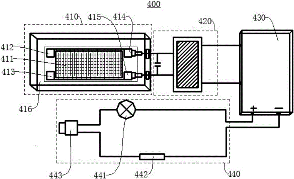
[0038] figure 2 for figure 1 For the structural schematic diagram of the medium piezoelectric ceramic fiber power generation system 400, please refer to figure 2 .

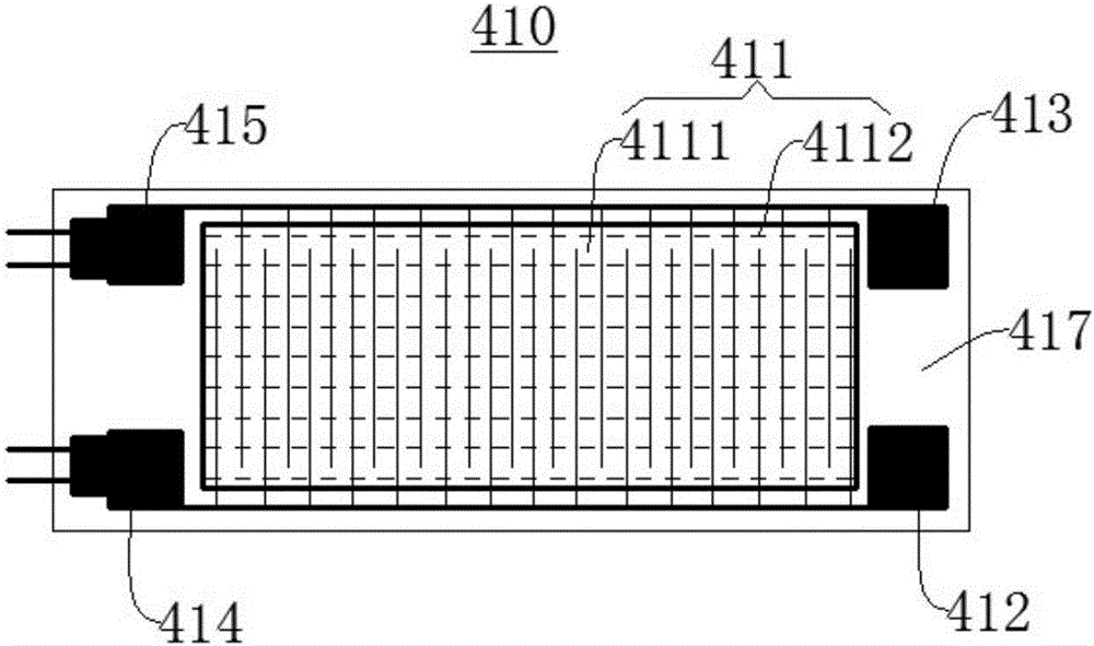
[0039] The piezoelectric ceramic fiber power generation system 400 includes a piezoelectric ceramic fiber driver 4...

no. 2 example

[0055] The power generation tire provided in this embodiment includes a tire body and the piezoelectric ceramic fiber power generation system 400 in the first embodiment. The piezoelectric ceramic fiber driver 410, the electric energy collection system 420 and the electric energy storage system 430 of the piezoelectric ceramic fiber power generation system 400 are arranged inside the tire body, and the electric energy utilization system 440 is arranged outside the tire body. The specific arrangement form between the piezoelectric ceramic fiber power generation system 400 and the tire body is similar to the arrangement form between the piezoelectric ceramic fiber power generation system 400 and the shoe sole 300 in the first embodiment, and will not be repeated here.

[0056] The power generation tire provided in this embodiment deforms during rotation, and the piezoelectric ceramic fiber composite material 411 inside it deforms accordingly to generate electric charges, thereby ...


PUM


Abstract

The invention provides a piezoelectric ceramic fiber power generation system, a pair of power generation shoes and a power generation tire, and relates to the technical field of piezoelectric recycling and conversion. The piezoelectric ceramic fiber power generation system comprises a piezoelectric ceramic fiber driver, an electric energy collection system, an electric energy storage system and an electric energy using system, wherein the piezoelectric ceramic fiber driver comprises a piezoelectric ceramic fiber composite material; the electric energy collection system is electrically connected with the piezoelectric ceramic fiber driver, and is used for collecting electric energy produced by the piezoelectric ceramic fiber composite material; the electric energy storage system is electrically connected with the electric energy collection system, and is used for storing electric energy collected by the electric energy collection system; the electric energy using system is electrically connected with the electric energy storage system, and is used for utilizing the electric energy stored by the electric energy storage system to work. The piezoelectric ceramic fiber power generation system has the advantage that the electric energy is produced by utilizing the deformation of the piezoelectric ceramic fiber composite material, and is finally provided for other electric appliance equipment to use, so as to effectively convert the waste mechanical energy into electric energy.

Description

technical field [0001] The invention relates to the technical field of piezoelectric recycling and transformation, in particular to a piezoelectric ceramic fiber power generation system, power generation shoes and power generation tires. Background technique [0002] In daily life, when people are exercising, such as walking or running, the bottom of the shoe will bend to generate mechanical energy. In addition, for some moving parts, mechanical energy will be generated during the working process, for example, vehicle tires will be deformed during the rotation process, which will generate mechanical energy. Whether the mechanical energy produced by shoes or tires will be lost in the air in vain. That is to say, existing moving parts such as shoes and tires fail to collect and utilize the mechanical energy produced by them, resulting in energy waste. [0003] Therefore, it is an urgent technical problem to design a system that can automatically collect and utilize the mecha...

Claims


Application Information

Patent Timeline
Patent Type & Authority Applications(China)
IPC IPC(8): H02J7/32H02N2/18A43B3/00B60C19/00
CPCH02N2/183B60C19/00H02J7/32A43B3/38
Inventor 杜建周李运平潘国翔朱孔军裘进浩季宏丽
Owner 盐城宇欣陶瓷科技有限公司
Learn More