
Industrial Cloth Laminating Machine

A technology of industrial cloth and laminating machine, which is applied in the directions of lamination device, lamination auxiliary operation, lamination, etc., can solve the problems of complex production process of industrial cloth, prolonging the processing time of cloth, reducing the production efficiency of cloth, etc. Flexible production methods, reduced installation and maintenance difficulties, and time-saving effects

Active Publication Date: 2017-06-23
HUBEI JINLONG NEW MATERIALS
View PDF4 Cites 2 Cited by
  • Summary
  • Abstract
  • Description
  • Claims
  • Application Information

AI Technical Summary

Problems solved by technology

[0003] The manufacturing process of industrial cloth is different according to its use. Coated cloth only needs to dip and dry the surface of the base cloth, while coated industrial cloth needs to be laminated with different coatings on the coated cloth. film, some industrial cloths that need to have self-cleaning function need to coat the surface treatment agent on the surface of the coated cloth, and the mesh cloth needs to coat different substrates on the surface of the base cloth, so that the production plant must at least Equipped with full coating function machine, coating plus lamination function machine, full lamination function machine and coating plus surface treatment function machine to meet the demand, which not only greatly increases the purchase cost of the factory, but also some industrial The cloth production process is relatively complicated and needs to be processed on different machines. During the transfer process of the cloth, a little carelessness will cause damage and pollution to the cloth, and the transfer of the cloth also prolongs the processing time of the cloth and reduces the production of the cloth. efficiency

Method used


Image

  • Industrial Cloth Laminating Machine
  • Industrial Cloth Laminating Machine
  • Industrial Cloth Laminating Machine

Examples


Embodiment Construction

[0025] Below in conjunction with accompanying drawing description and specific embodiment, the present invention will be described in further detail:

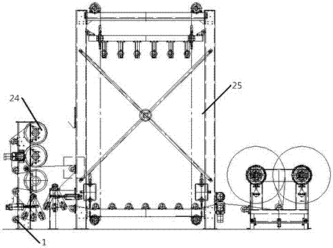
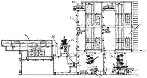
[0026] see Figure 1-Figure 2 , an industrial cloth laminating machine, including a cloth feeding mechanism 2, a coating mechanism 3, a film pasting mechanism 4 and a material receiving mechanism 5 connected in series by a feeding roller table 1, and the cloth feeding mechanism 2 includes a cloth ironing mechanism Device 24, the cloth ironing device 24 is close to the side of the coating mechanism 3, the coating mechanism 3 includes a vertical oven 6, a horizontal oven 7 and a dipping device 8, and the film sticking mechanism 4 includes a sending table 9, The film processing device 10 and the large cylinder 11, the material receiving mechanism 5 includes a total pressure table 12, a cooling belt 13 and a winding device 14, in order to ensure that the final finished selvedge is neat, the cooling belt 13 and the winding device 14...


PUM


Abstract

The invention relates to an industrial fabric laminating machine. The industrial fabric laminating machine is characterized by comprising a fabric delivering mechanism, a coating mechanism, a film sticking mechanism and a material collecting mechanism which are serially connected together through a material pass roller table, wherein the coating mechanism comprises a vertical drying oven, a horizontal drying oven and an impregnation device, the film sticking mechanism comprises a sending table, a film treatment device and a large cylinder, and the material collecting mechanism comprises a main press table, a cooling belt and a take-up device. The industrial fabric laminating machine is simple in structure and very high in production efficiency and can meet various industrial fabric production demands, and the production cost is also remarkably reduced.

Description

technical field [0001] The invention relates to the technical field of industrial cloth production, in particular to an industrial cloth laminating machine. Background technique [0002] There are many kinds of industrial cloth, which can be roughly divided into polypropylene filter cloth, dust filter bag, monofilament filter cloth, non-woven filter cloth, etc. according to different materials and uses. Industrial cloth needs to be resistant to acid and alkali, wear resistance, and good conductivity. In recent years, the emergence of high-performance new synthetic materials has accelerated the development of industrial canvas materials. [0003] The manufacturing process of industrial cloth is different according to its use. Coated cloth only needs to dip and dry the surface of the base cloth, while coated industrial cloth needs to be laminated with different coatings on the coated cloth. film, some industrial cloths that need to have self-cleaning function need to coat the...

Claims


Application Information

Patent Timeline
Patent Type & Authority Patents(China)
IPC IPC(8): B32B37/00B32B38/00
CPCB32B37/00B32B38/00
Inventor 饶金才李祥勇
Owner HUBEI JINLONG NEW MATERIALS
Learn More