
Automatic installation device of protective sleeve of capacitor

A technology for capacitor protection and automatic installation, which is applied in packaging capacitor devices, capacitors, and capacitor manufacturing. It can solve the problems of manual operation error, capacitor pins are easy to be bent, and affect the protection effect, so as to improve the protection effect. High reliability, time and cost saving effect

Inactive Publication Date: 2017-01-11
铜陵市铜创电子科技有限公司
View PDF3 Cites 3 Cited by
  • Summary
  • Abstract
  • Description
  • Claims
  • Application Information

AI Technical Summary

Problems solved by technology

[0002] A capacitor is an electronic component used for energy storage, including a capacitor body and two pins. In order to avoid the problem that the capacitor pins are easy to be bent, two protective sleeves are usually inserted on the capacitor pins to protect The sleeve has elastic deformation, and the protective sleeve is provided with an accommodating groove for accommodating pins. The accommodating groove is arranged along the axial direction of the protective sleeve, and the side wall of the protective sleeve is provided with a cutout in the axial direction, and the cutout is communicated with the accommodating groove. In the prior art, when installing the capacitor pins into the protective sleeve, the cutout of the protective sleeve is usually opened manually, and then the capacitor pins are inserted into the receiving groove of the protective sleeve through the cutout. The method has high labor cost and high labor intensity, and manual operation is prone to errors, which will affect the protection effect

Method used


Image

  • Automatic installation device of protective sleeve of capacitor
  • Automatic installation device of protective sleeve of capacitor

Examples


Embodiment Construction

[0014] In order to make the technical means, creative features, goals and effects of the invention easy to understand, the present invention will be further elaborated below in conjunction with specific illustrations.

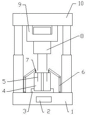
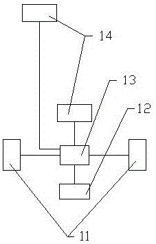
[0015] Such as figure 1 and figure 2 As shown, an automatic capacitor protection sleeve installation device includes an upper seat 10 and a lower seat 1, two cylinder rods are arranged between the upper seat 10 and the lower seat 1, and a placement groove 3 is provided above the lower seat 1, and the placement groove 3 is located at In the middle of the two oil cylinder rods, mechanical arms 6 are provided on both sides of the placement groove 3, rubber blocks 7 are provided on the mechanical arm 6, and a clamping device 9 is provided under the upper seat 10, and a protective sleeve 4 is placed inside the placement groove 3. There is a cutout 5 on the protective sleeve 4, and the capacitor 8 is clamped on the clamping device 9. The position of the lead wire o...


PUM


Abstract

The invention discloses an automatic installation device of the protective sleeve of a capacitor. The automatic installation device comprises an upper seat and a lower seat; two oil cylinder rods are arranged between the upper seat and the lower seat; an accommodating groove is arranged on the lower seat; the accommodating groove is located between the two oil cylinder rods; one mechanical arm is arranged at each of two sides of the accommodating groove; the mechanical arms are provided with rubber clamping blocks; a clamping device is arranged below the upper seat; the protective sleeve is arranged in the accommodating groove; and a notch is formed in the protective sleeve; and the capacitor is clamped on the clamping device; and the position of the lead-out line of the capacitor is corresponding to the position of the notch in a vertical direction. The device has the advantages of high automation degree, high work efficiency and high installation accuracy. With the device adopted, the installation work of the protective sleeve of the capacitor can be completed quickly, manpower installation costs can be decreased, and the protection effect of the protective sleeve can be improved.

Description

technical field [0001] The invention relates to the technical field of capacitor processing equipment, and more specifically, to an automatic installation device for a capacitor protection sleeve. Background technique [0002] A capacitor is an electronic component used for energy storage, including a capacitor body and two pins. In order to avoid the problem that the capacitor pins are easy to be bent, two protective sleeves are usually inserted on the capacitor pins to protect The sleeve has elastic deformation, and the protective sleeve is provided with an accommodating groove for accommodating pins. The accommodating groove is arranged along the axial direction of the protective sleeve, and the side wall of the protective sleeve is provided with a cutout in the axial direction, and the cutout is communicated with the accommodating groove. In the prior art, when installing the capacitor pins into the protective sleeve, the cutout of the protective sleeve is usually opened...

Claims


Application Information

Patent Timeline
IPC IPC(8): H01G13/00
CPCH01G13/003
Inventor 沈艺辉
Owner 铜陵市铜创电子科技有限公司
Learn More