


Quick Research
Generate reliable direction feasibility study reports for your R&D in just a few steps.

Technical Q&A
Discover and master advanced knowledge NOW. Basics, ideas, possibilities, all at once.

Find Solutions
As an expert in R&D theories, this can generate solutions to your technical problems instantly.

Evaluate Feasibility
Analyze your overall solution with one click, know your potential R&D risks in advance.

Monitor Landscape
Get weekly tech updates, stay abreast of the latest tech innovations and key insights.
Gas cooker and its components
A technology for gas stoves and components, applied in the field of gas stoves, can solve the problems of being difficult to clean and easy to become a dead corner of hygiene at the screw.
- Summary
- Abstract
- Description
- Claims
- Application Information
AI Technical Summary
Problems solved by technology
Method used
Image

Examples
Embodiment 1
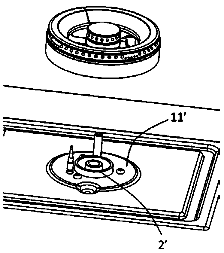
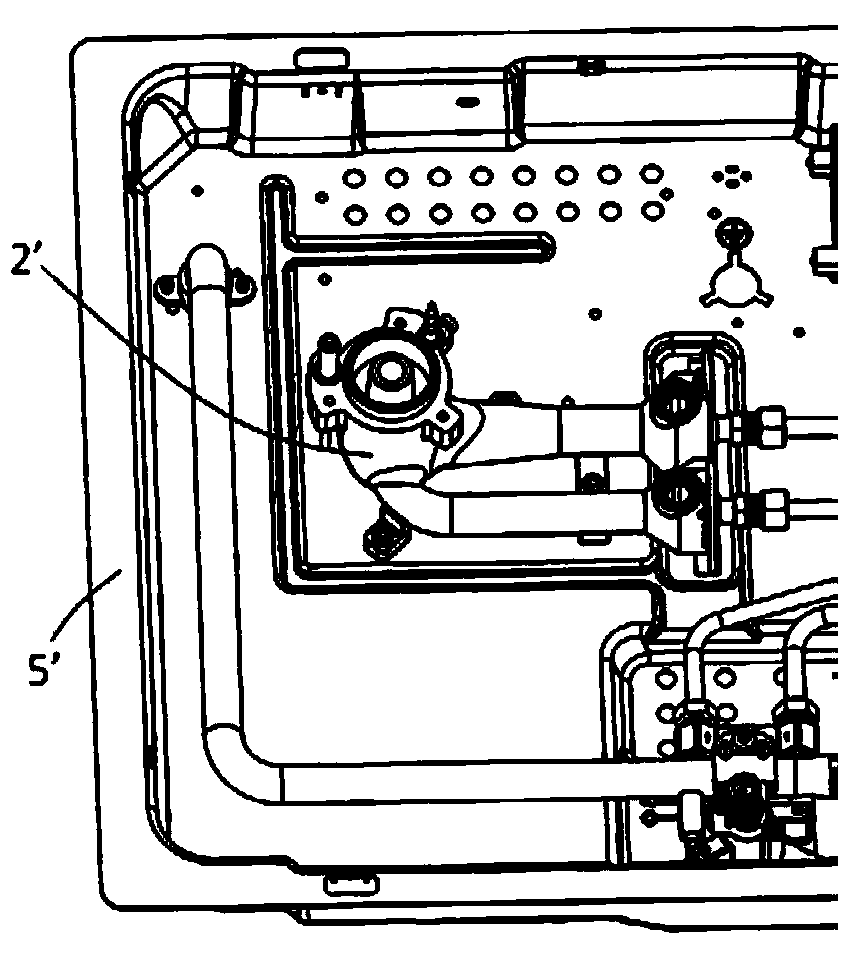
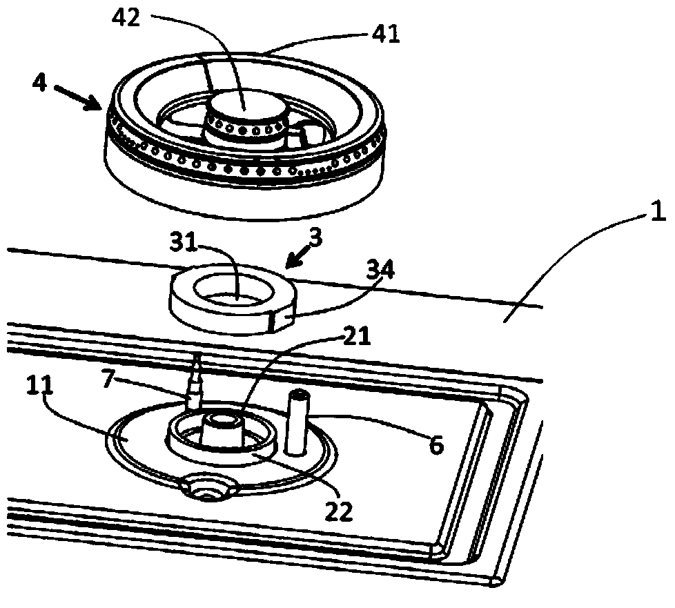
[0042] The present invention provides an embodiment of a gas stove, which includes a gas stove assembly, an ignition needle 6 and a thermocouple 7.
[0043] Gas stove components, including panel 1, burner base 2, fixing parts 3, burner 4 and bottom shell, such as Figure 3 to 5 Shown. The panel 1 includes a liquid pan 11 made of stainless steel, and the liquid pan 11 is provided with a through hole. The bottom of the burner base 2 is fixed to the bottom shell. Both the ignition needle 6 and the thermocouple 7 are fixed on the base 2 of the furnace head, and the liquid pan 11 is provided with holes for passing the ignition needle 6 and the thermocouple 7 respectively.
[0044] The fixing member 3 has a circular ring structure and adopts an integrally formed structure. The fixing member 3 includes a hollow portion 31, a circular groove 32 and two symmetrically arranged clamping portions 34, such as Image 6 with 7 Shown. The clamping portion 34 adopts a convex structure, such as ...
Embodiment 2
[0052] The present invention also proposes another gas stove embodiment 2, which is obtained by further improvement on the basis of the above gas stove embodiment 1. The main differences between this gas stove embodiment 2 and the above gas stove embodiment 1 are as follows.
[0053] The fixing member 3 of the gas stove assembly of the gas stove embodiment 2 has a nut structure, such as Picture 8 with 9 Shown. The protrusion 24 of the outer tube 22 is provided with an external thread. The fixing member 3 is provided with an internal thread 33 matching the external thread of the protrusion 24, and the internal thread 33 surrounds the hollow part 31. The fixing member 3 is fixed to the protruding portion 24 from top to bottom through a threaded connection. The edge 12 of the through hole is squeezed and fixed between the fixing member 3 and the stop 23 of the outer tube 22, and the top end of the fixing member 3 It is at the same level as the top end of the protrusion 24, and th...
PUM
 Abstract
Description
Claims
Application Information
 - R&D Engineer
- R&D Manager
- IP Professional
- Industry Leading Data Capabilities
- Powerful AI technology
- Patent DNA Extraction
Browse by: Latest US Patents, China's latest patents, Technical Efficacy Thesaurus, Application Domain, Technology Topic, Popular Technical Reports.
© 2024 PatSnap. All rights reserved.Legal|Privacy policy|Modern Slavery Act Transparency Statement|Sitemap|About US| Contact US: help@patsnap.com