Additional shaft clamping mechanism of gantry machining machine

A clamping mechanism and additional shaft technology, applied in metal processing mechanical parts, metal processing equipment, manufacturing tools, etc., can solve the problems of unstable clamping force and large volume, and achieve the effect of stable clamping and reducing volume.

Inactive Publication Date: 2017-01-11
星视野精密机械股份有限公司
View PDF5 Cites 0 Cited by
  • Summary
  • Abstract
  • Description
  • Claims
  • Application Information

AI Technical Summary

Problems solved by technology

[0004] In view of this, the present invention provides an additional shaft clamping mechanism of a gantry processing machine to improve the prior art. The clamping mechanism between the main shaft and the additional shaft of the existing gantry processing machine has less stable clamping force and Problems such as large size

Method used


Image

  • Additional shaft clamping mechanism of gantry machining machine
  • Additional shaft clamping mechanism of gantry machining machine
  • Additional shaft clamping mechanism of gantry machining machine

Examples


Embodiment Construction

[0031] In order to enable your review committee to have a further understanding and recognition of the features and characteristics of the present invention, the following preferred embodiments are listed below and described as follows with the help of drawings:

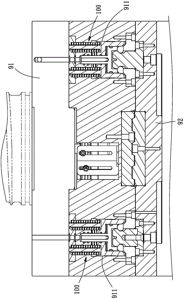
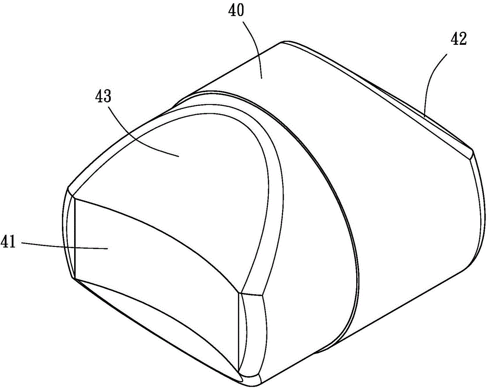
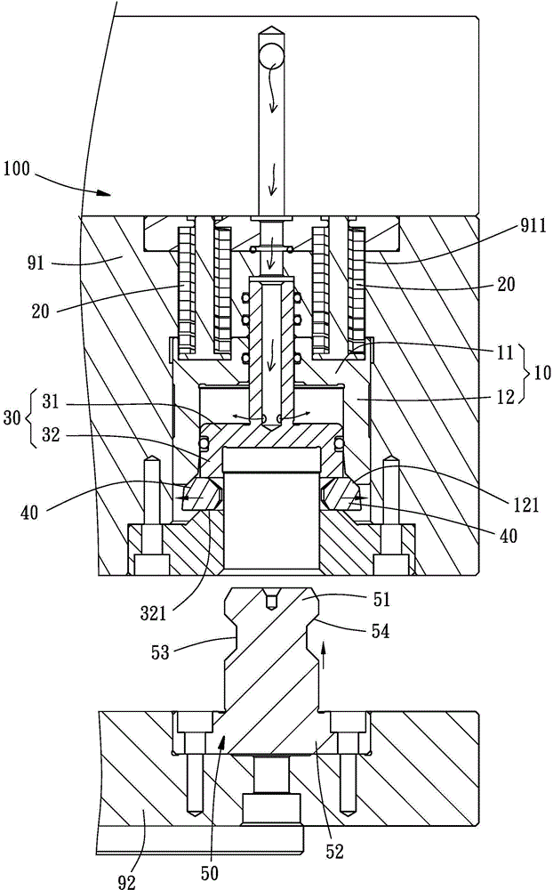
[0032] see Figure 1 to Figure 5 , is an additional shaft clamping mechanism 100 of a gantry processing machine provided by a preferred embodiment of the present invention, used to combine and separate a main shaft 91 and an additional shaft 92, which mainly includes an outer cover body 10, several The spring 20, an inner cover body 30, some clip blocks 40 and a positioning column 50, wherein:

[0033] see Figure 1 to Figure 5 , the outer cover body 10 is movably arranged in a chamber 911 opened by the main shaft 91, and can be reciprocated from an upper top position to a lower push position by an external force. The outer cover body 10 has an outer cover top The wall 11 and an outer cover peripheral wall 12 integ...


PUM


Abstract

The invention provides an additional shaft clamping mechanism of a gantry machining machine. The mechanism comprises an outer cover body, multiple springs, an inner cover body, multiple clamping blocks and a positioning column; the outer cover body is arranged on a main shaft, and can perform a reciprocating displacement between an upward ejecting position and a downward pushing position; the multiple springs are butted between the main shaft and the outer cover body; the inner cover body is positioned in the outer cover body, and is fixedly connected with the main shaft; the inner cover body is provided with multiple displacement holes annularly arranged at equal intervals; the multiple clamping blocks are respectively positioned in the displacement holes, and perform a reciprocating displacement between a clamping position and a releasing position; clamping block wedge surfaces are arranged at the inner ends of the clamping blocks; the positioning column has a head part, a body part, and a neck part connected between the head part and the body part; a positioning column wedge surface is arranged between the neck part and the head part; the body part is locked on an additional shaft; and when the outer cover body is displaced from the upward ejecting position to the downward pushing position, the outer cover body pushes the clamping blocks to move from the releasing position to the clamping position, the clamping block wedge surfaces are butted to the positioning column wedge surface, and the additional shaft is combined with the main shaft.

Description

technical field [0001] The invention relates to a gantry processing machine, more specifically, an additional shaft clamping mechanism of the gantry processing machine. Background technique [0002] By the way, when the gantry processing machine intends to perform processing different from the axial direction of the main shaft, an additional axis is generally combined with the main shaft to achieve the purpose of processing in different axial directions. [0003] However, in order to achieve the purpose of combining or separating the additional shaft and the main shaft, a large number of clamping mechanisms must be provided between the main shaft and the additional shaft. However, as disclosed in Taiwan Patent Announcement No. M446674, I316441, and 392546, its clamping structure mainly utilizes a jaw on the main shaft to clamp a cone seat on the additional shaft, but this simple advantage relies on The method of clamping force is not stable, and it is easy to cause loosenes...

Claims


Application Information

Patent Timeline
Patent Type & Authority Applications(China)
IPC IPC(8): B23B19/02
CPCB23Q1/703
Inventor 陈庆癸张展谋
Owner 星视野精密机械股份有限公司
Why Eureka
Try Eureka