
Copper bar shunting clamp assembly

A component and copper chuck technology, applied in the direction of electrical components, electrical component connections, circuits, etc., can solve the problems of self-weight, single-angle operation, etc., achieve multi-angle operation, improve production efficiency, and reduce safety risks.

Active Publication Date: 2017-01-04
GUANGZHOU POWER SUPPLY BUREAU GUANGDONG POWER GRID CO LTD
View PDF9 Cites 0 Cited by
  • Summary
  • Abstract
  • Description
  • Claims
  • Application Information

AI Technical Summary

Problems solved by technology

However, the wire palms are generally located at a height of 3 to 10 meters above the ground, and the wire palms have various forms, such as horizontal arrangement, vertical arrangement, and corner arrangement; while the existing copper bar shunt clamps are usually made of steel materials, It is heavy and can only be operated at a single angle; when the site conditions do not permit, it is necessary to use a high-altitude vehicle to install a temporary copper bus shunt clip for the wire palm

Method used

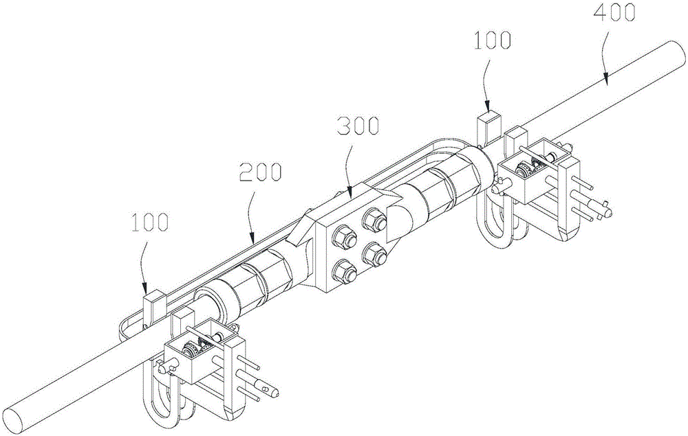
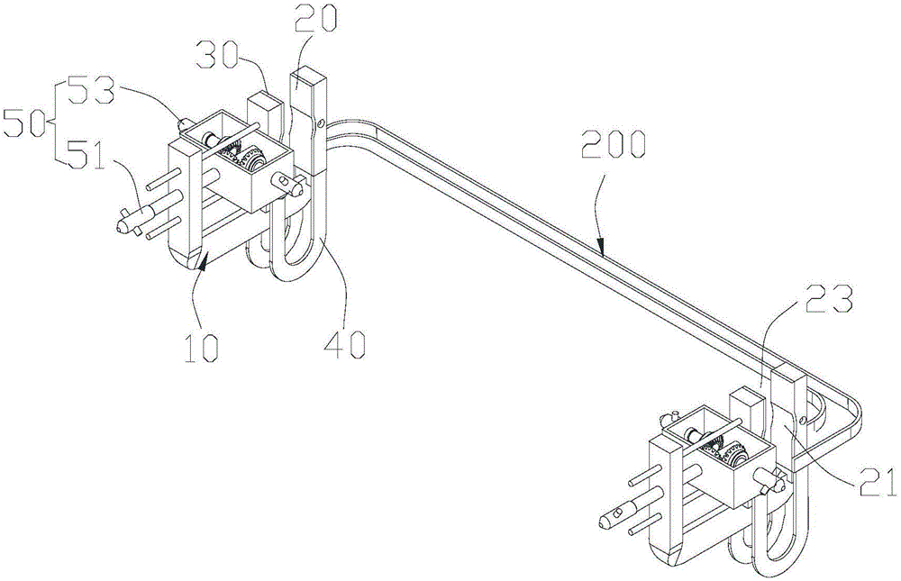
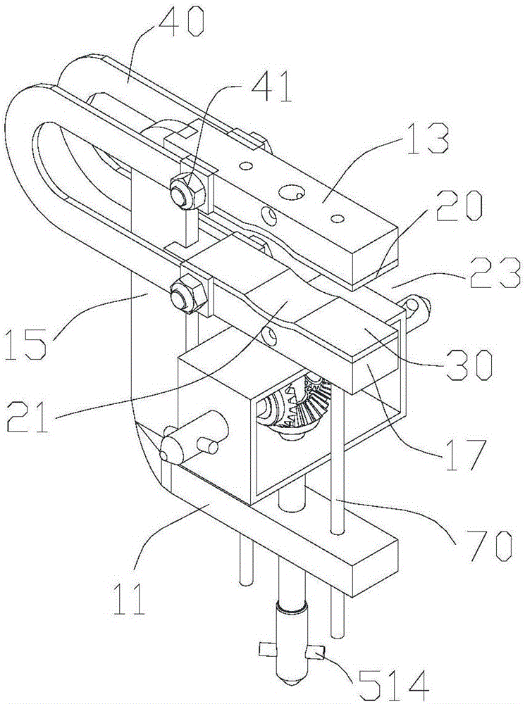

Image

  • Copper bar shunting clamp assembly
  • Copper bar shunting clamp assembly
  • Copper bar shunting clamp assembly

Examples


Embodiment Construction

[0020] In order to facilitate the understanding of the present invention, the present invention will be described more fully below with reference to the associated drawings. Preferred embodiments of the invention are shown in the accompanying drawings. However, the present invention can be embodied in many different forms and is not limited to the embodiments described herein. On the contrary, these embodiments are provided to make the understanding of the disclosure of the present invention more thorough and comprehensive.

[0021] It should be noted that when an element is referred to as being “fixed” to another element, it can be directly on the other element or there can also be an intervening element. When an element is referred to as being "connected to" another element, it can be directly connected to the other element or intervening elements may also be present.

[0022] Unless otherwise defined, all technical and scientific terms used herein have the same meaning as...


PUM


Abstract

A copper bar shunting clamp assembly comprises two copper bar shunting clamps and a shunting line, wherein each copper bar shunting clamp comprises a clamping body, an upper copper clamp head, a lower copper clamp head, a copper woven belt and an adjustment device, the upper copper clamp head and the lower copper clamp head are respectively arranged at two ends, opposite to each other, of the clamping head, and clamping grooves are sunken and formed in surfaces opposite to the upper copper clamp head and the lower copper clamp head, the adjustment device is arranged on the clamping head and comprises a main adjustment assembly and an auxiliary adjustment assembly, one end of the main adjustment assembly is connected with the lower copper clamp head, and the lower copper clamp head can be pushed to get close to or deviate from the direction of the upper copper clamp head to move under the driving of an external force or the auxiliary adjustment assembly so that clamping positions are formed by the two clamping grooves. In the copper bar shunting clamp assembly, the two copper bar shunting clamps are correspondingly clamped on crimping ends of two line palms vertically connected with respective wires, the operation process can be directly performed on the ground, the production efficiency is improved, and the safety risk is reduced; and meanwhile, each copper bar shunting clamp is further provided with the main adjustment assembly and the auxiliary adjustment assembly, multi-angle operation is achieved, and the copper bar shunting clamp assembly is convenient and rapid.

Description

technical field [0001] The invention relates to the field of electric equipment, in particular to a copper bar shunt clip assembly clamped between two vertical wire palms and respective wire crimping ends. Background technique [0002] At present, the wire palms used for high-voltage wire connection in outdoor equipment are affected by the hot and humid weather in southern my country, such as humidity, heat, aging, rust and other factors, which will reduce the service life of the wire palms. In addition, affected by the crimping process and installation process, there may be a problem of excessive contact resistance at the crimping end of the wire palm and the wire, and the long-term high-voltage and high-current working environment may even lead to poor contact of the wire palm, heating, and burning. Wire palms or wires can cause vicious events such as disconnection of wires in the power system, power outages in accidents, and line tripping. [0003] During the long-term o...

Claims


Application Information

Patent Timeline
Patent Type & Authority Applications(China)
IPC IPC(8): H01R11/14
CPCH01R11/14
Inventor 刘威葳陈宇昇朱信红冯玉辉周述江黄智聪张冲全磊朱博蔡润庆俞思帆陈丽萍
Owner GUANGZHOU POWER SUPPLY BUREAU GUANGDONG POWER GRID CO LTD
Learn More