
Rotation control method of 3D laser scanner

A three-dimensional laser and control method technology, applied in the field of optical scanning, can solve the problems of point cloud randomness, two-axis rotation mechanism not synchronously controlling the horizontal rotation part and the vertical rotation part, etc.

Active Publication Date: 2018-09-14
WUHAN HI TARGET DIGITAL CLOUD TECH CO LTD
View PDF5 Cites 0 Cited by
  • Summary
  • Abstract
  • Description
  • Claims
  • Application Information

AI Technical Summary

Problems solved by technology

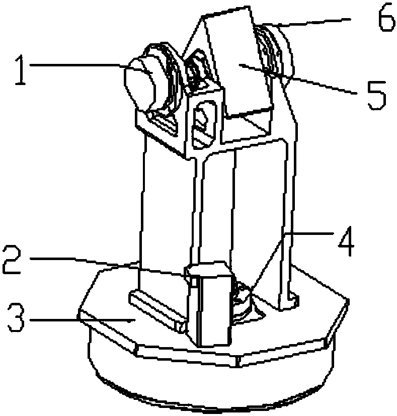
[0008] The purpose of the present invention is to provide a rotation control method of a three-dimensional laser scanner to solve the problem that most of the two-axis rotation mechanisms of the three-dimensional laser scanner in the prior art do not synchronously control the rotation of the horizontal rotation part and the vertical rotation part. Technical problems presenting randomness in a line

Method used


Image

  • Rotation control method of 3D laser scanner
  • Rotation control method of 3D laser scanner
  • Rotation control method of 3D laser scanner

Examples


Embodiment Construction

[0034] It should be noted that, in the case of no conflict, the embodiments of the present invention and the features in the embodiments can be combined with each other. The present invention will be described in detail below with reference to the accompanying drawings and examples.

[0035] In the description of the present invention, it should be noted that unless otherwise specified and limited, the term "connection" should be understood in a broad sense, for example, it can be a fixed connection, a detachable connection, or an integral connection; It can be a mechanical connection or an electrical connection; it can be a direct connection or an indirect connection through an intermediary, and it can be the internal communication of two components. Those of ordinary skill in the art can understand the specific meanings of the above terms in the present invention in specific situations.

[0036] Such as Figure 1 to Figure 6 As shown, the rotation control method of the thr...


PUM


Abstract

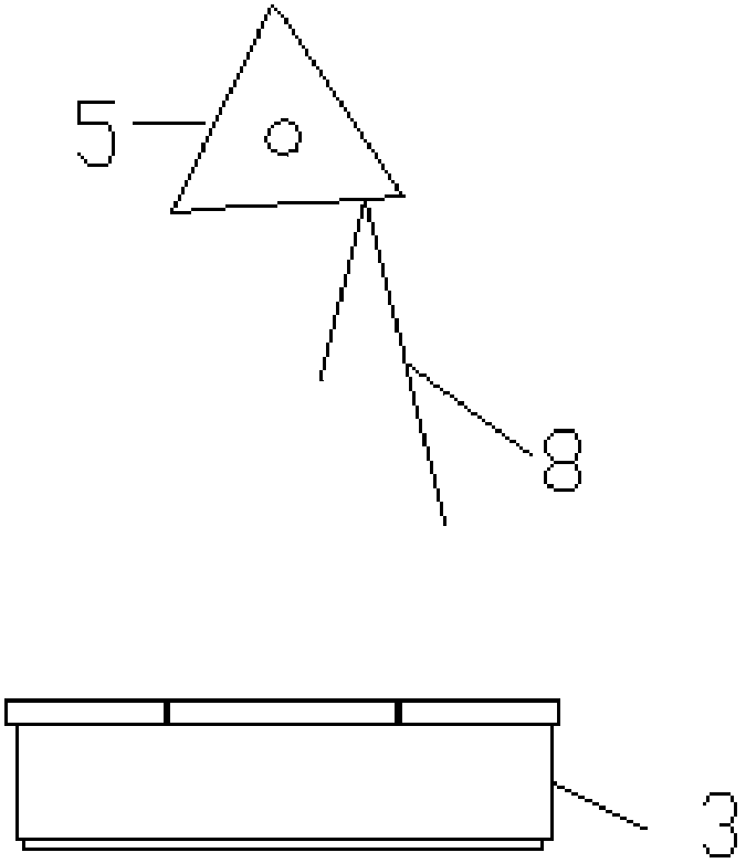
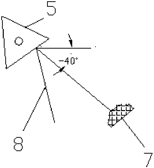
The invention discloses a rotation control method of a three-dimensional laser scanner. The method comprises the steps that: (S1) a prism rotates, before an angle feedback module detects that the first surface of the prism is about to enter an valid angle, and the angle feedback module feeds a signal to a single chip microcomputer to control a horizontal rotation platform to stop rotation; (S2) the prism continues to rotate, the angle feedback module detects that the first surface of the prism rotates for a valid angle and is in an invalid angle, the angle feedback module feeds a signal to the single chip microcomputer to control the horizontal rotation platform to rotate for a horizontal stepping angle and then stop; and (S3) the prism continues to rotate, before the angle feedback module detects that the second surface of the prism is about to enter a valid angle, the angle feedback module feeds a signal to the single chip microcomputer to control the horizontal rotation platform to stop rotation, and the above step is repeated until the prism is rotated for a circle. According to the method, the rotation speed and rotation angle of the horizontal rotation platform are controlled by the angle n synchronous coordination control of the prism so as to achieve the effect of optimizing scanner point cloud.

Description

technical field [0001] The invention relates to the field of optical scanning technology, in particular to a rotation control method of a three-dimensional laser scanner. Background technique [0002] With the development of automation control technology, more and more rotating systems are used in our life and work. In the three-dimensional laser scanning equipment, a two-axis electric rotation mechanism is required to make each laser beam hit a different spatial position. We need to rotate the horizontal rotating table and the vertical prism at the same time, and record the horizontal angle and vertical angle of each laser beam, and combine the distance to establish a polar coordinate system to solve the three-dimensional point cloud data. Therefore, a two-axis rotating mechanism with uniformly adjustable speed and stable operation without shaking is very important in a three-dimensional laser scanner. [0003] The 3D laser scanners currently on the market have the follow...

Claims


Application Information

Patent Timeline
Patent Type & Authority Patents(China)
IPC IPC(8): G01B11/24
CPCG01B11/24
Inventor 陆晓明刘漫漫符运强陈小宇毛庆洲胡庆武宫汉鲁王晖
Owner WUHAN HI TARGET DIGITAL CLOUD TECH CO LTD
Learn More