
Mixed water direct heat supply operation system

An operation system and water mixing technology, applied in heating systems, hot water central heating systems, household heating, etc., can solve the problem of low water supply temperature in the secondary network, heavy maintenance workload of heat exchange stations, and heat exchange of heat exchange equipment. Efficiency reduction and other issues, to achieve the effect of reducing equipment maintenance costs, improving heating quality, and increasing transportation capacity

Inactive Publication Date: 2017-01-04
HARBIN THERMAL POWER CO LTD
View PDF0 Cites 3 Cited by
  • Summary
  • Abstract
  • Description
  • Claims
  • Application Information

AI Technical Summary

Problems solved by technology

[0006] 1. There are many equipments in the heat exchange station, and the heat exchanger and water supply system have been added. The initial investment in the construction of the heat exchange station is relatively large, and the building area required for the heat exchange station is relatively large
[0007] 2. The maintenance workload in the heat exchange station is heavy. When the water quality is not good, the heat exchanger is often blocked, and the heat exchanger needs to be cleaned frequently
[0008] 3. As the running time increases, the heat exchange efficiency of the heat exchange equipment gradually decreases, the water supply temperature of the secondary network is low, and the indoor temperature of some users does not meet the standard
[0009] 4. The operation of the heat exchange station is often a large flow rate with a small temperature difference and a large power consumption
[0010] 5. Due to hydraulic imbalance, some heat exchange stations have insufficient primary network flow and the heating quality is not up to standard
[0011] 6. The pipe diameter of the branch line of the primary network is relatively large

Method used


Image

  • Mixed water direct heat supply operation system
  • Mixed water direct heat supply operation system

Examples


Embodiment Construction

[0021] The present invention will be described in further detail below in conjunction with the accompanying drawings: the present embodiment is implemented on the premise of the technical solution of the present invention, and detailed implementation is provided, but the protection scope of the present invention is not limited to the following embodiments.

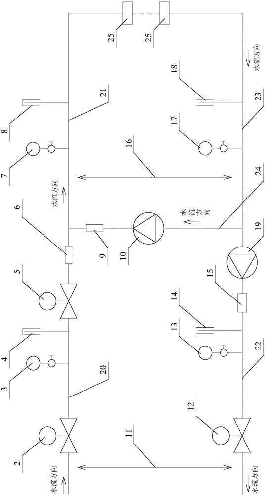
[0022] Such as figure 2 As shown, a mixed water direct heating operation system involved in this embodiment includes: primary network electric ball valve 2, primary network water supply pressure gauge 3, primary network water supply temperature gauge 4, primary network electric regulating valve 5, primary network Network water supply flow meter 6, secondary network water supply pressure gauge 7, secondary network water supply temperature gauge 8, mixed water flow meter 9, mixed water pump 10, primary network electric ball valve 2 12, primary network return water pressure gauge 13, primary network return Water temperature ...


PUM


Abstract

The invention provides a mixed water direct heat supply operation system, and belongs to the technical field of heat supply systems. One end of a mixed water tube communicates with the tail end of a primary network water supply tube, and the other end of the mixed water tube communicates with the primary end of the primary network water supply tube. One end of a secondary network water supply tube communicates with the tail end of the primary network water supply tube, and the other end of the secondary network water supply tube communicates with the primary end of a heat user. One end of a secondary network water returning tube communicates with the primary end of a primary network water returning tube, and the other end of the secondary network water returning tube communicates with the tail end of the heat user. According to the mixed water direct heat supply operation system, the temperature of primary network returning water is lowered by about 15 DEG C, the electricity saving amount of a heating station reaches 60%, equipment maintenance cost is lowered by 80% per year, the conveying capacity of a primary tube network is improved by 20%, heat supply quality is greatly improved, and the initial cost of equipment is saved.

Description

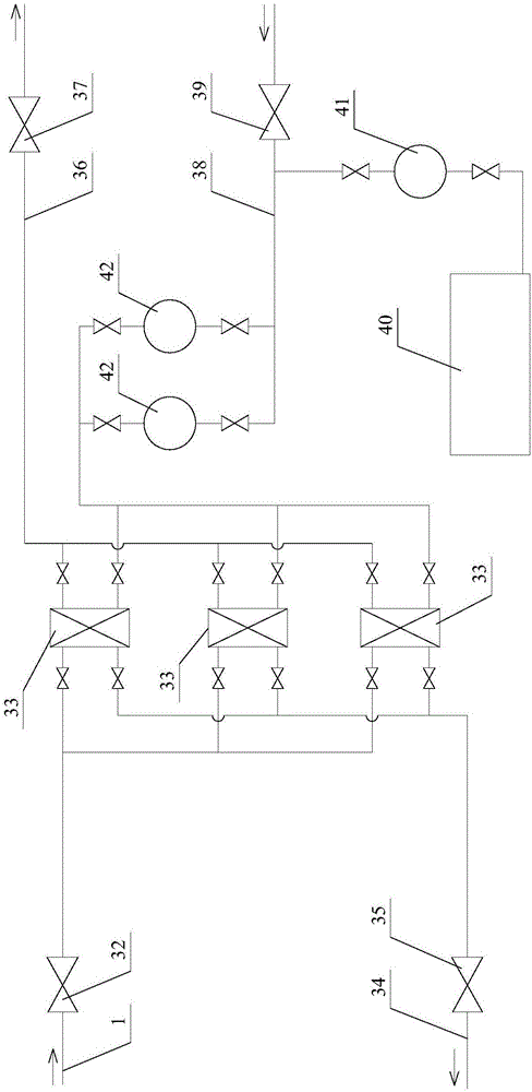
technical field [0001] The invention relates to a mixed water direct heating operation system, which belongs to the technical field of heating systems. Background technique [0002] The original heating network system in the heating area of ​​most thermal power plants is a high-temperature water heating system of central heating "cogeneration". Heating for system users. The secondary heat exchange station adopts plate heat exchanger for secondary heat exchange, and the water circulation of the secondary network system adopts the secondary pump circulation system to provide heat for users. The constant pressure of the secondary network adopts the mechanical constant pressure method, and the heating network system is a typical indirect heating system. [0003] The heating system technological process of prior art (as figure 1 Shown) is: the high-temperature hot water of the primary main heating network enters the heat exchange station through the primary water supply pipe 1...

Claims


Application Information

Patent Timeline
Patent Type & Authority Applications(China)
IPC IPC(8): F24D3/10F24D3/02F24D19/10
CPCF24D3/1058F24D3/02F24D19/1009
Inventor 常立宏李运祥张慧燕
Owner HARBIN THERMAL POWER CO LTD
Learn More