Vane hand pump with siphon function

A vane-type, hand-operated pump technology, applied in the field of positive displacement pumps, can solve problems such as unfitness, long water discharge cycle, intermittent water flow, etc., and achieve the effects of improving the degree of generalization, eliminating noise and vibration, and saving production costs

Active Publication Date: 2018-11-27
陈兆红
View PDF5 Cites 0 Cited by
  • Summary
  • Abstract
  • Description
  • Claims
  • Application Information

AI Technical Summary

Problems solved by technology

[0002] At present, most of the known hand pumps are swing arm piston reciprocating manual pumps. This kind of pump has strong self-priming ability and simple structure, but the disadvantage is that one suction and one row, the water flow is intermittent, the water discharge cycle is long, and it does not have a siphon function.
However, the traditional vane pump also has its defects. First, the outer end surface of the vane and the inner surface of the pump body, as well as the two sides of the vane and the left and right stationary side plates all produce high-speed friction, resulting in heat generation, and even the transmission of medium. Vaporization; the second is the closed space surrounded by the outer circle of the rotor, the inner cavity of the pump body and the two blades. Its volume is constantly changing during operation. When the volume changes from large to small, it is easy to trap liquid. Due to the incompressibility of liquid , the excess liquid is forced out from the gap, resulting in noise and vibration; the above two defects make the pump only suitable for transporting oil with good lubricity, but not suitable for transporting water with poor lubricity. Suitable for use as a hand pump

Method used


Image

  • Vane hand pump with siphon function
  • Vane hand pump with siphon function
  • Vane hand pump with siphon function

Examples


Embodiment Construction

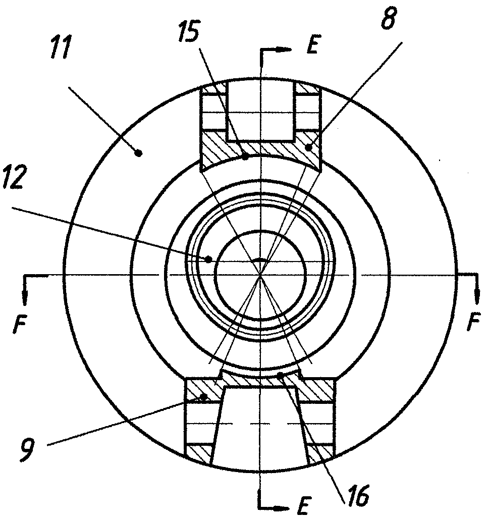
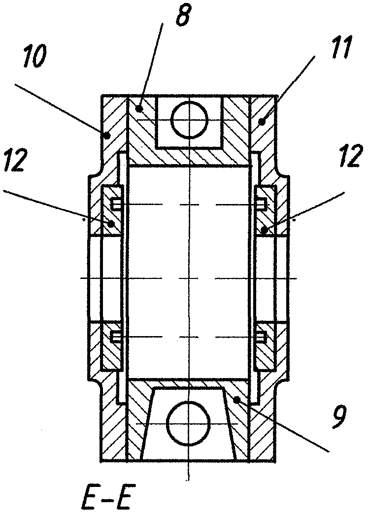
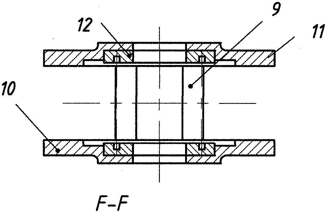
[0030] figure 1 Is a structural diagram of an embodiment of the present invention, figure 2 Yes figure 1 A-A section view, image 3 Yes figure 1 B-B cross-sectional view.

[0031] The figure shows that the pump body 1 with suction and discharge ports is equipped with a front pump cover 19 and a rear pump cover 20 on both sides. The inner cavity of the pump body 1 is equipped with a vane pump modular unit 5, which is composed of The pump chamber assembly 6 and the rotor assembly 7 are composed of two parts. The pump chamber assembly 6 is composed of four parts: the upper partition tongue 8, the lower partition tongue 9, the front partition 10 and the rear partition 11, which are fixedly installed Together, the upper partition tongue 8 and the lower partition tongue 9 separate the pump chamber into a low pressure zone and a high pressure zone. The front partition 10 and the rear partition 11 are equipped with three arcs coaxial with the rotor 2 toward the inner side of the rotor 2....


PUM


Abstract

A vane type hand pump with a siphon function comprises a pump body, a rotor, vanes and a pump shaft. A vane pump modular unit is mounted in an inner cavity of the pump body and comprises a pump chamber assembly and a rotor assembly, an arc-triangle equal-width cam trough plate serves as a guide mechanism of the vanes, and the rotor and two side plates are connected into a whole and synchronously rotate. Therefore, in operation, end faces and side faces of the vanes cannot emit heat due to friction, vibration and noise caused by fluid trap are avoided, and a switching valve is mounted in the modular unit. In the water delivery process, the vane type hand pump has the siphon function only when water level difference meets requirements and the switching valve is opened, and fluids are automatically discharged. Compared with a traditional reciprocating manual pump, the pump with the function can save half the time by absorbing the same capacity of water, rotation of a handle is more suitable for the operation habit of people as compared with vertical swing of a swing arm, people are not easily fatigued, and the pump can be conveniently and rapidly maintained only by replacing a module.

Description

Technical field [0001] The invention relates to a positive displacement pump, particularly a vane type hand pump with siphon function. Background technique [0002] Most of the currently known hand pumps are swing arm piston reciprocating hand pumps. Such pumps have strong self-priming ability and simple structure, but the disadvantages are that one sucks one row, the water flow is intermittent, the water discharge cycle is long, and does not have the siphon function. The vane pump, which is also a positive displacement pump, also has a good self-priming function and is very suitable for use as a hand pump. It consists of a pump body with suction and discharge ports, an offset rotor, and multiple blades inserted in the radial grooves of the rotor. It is composed of pump shaft, simple and compact structure, strong self-priming ability, stable liquid flow without pulse, and efficiency as high as 80%. It is widely used as an oil pump. However, the traditional vane pump also has its...

Claims


Application Information

Patent Timeline
Patent Type & Authority Patents(China)
IPC IPC(8): F04C2/344F04C15/00
CPCF04C2/3441F04C15/00F04C2240/10
Inventor 余文凌陈兆红
Owner 陈兆红
Why Eureka
Try Eureka