Conveying chain

A technology for conveying chains and chain links, applied in the field of chains, can solve problems such as inconvenience and waste, and achieve the effect of prolonging service life, ensuring normal use, and prolonging the use time of a single refueling.

Active Publication Date: 2017-01-04
江山永利百合实业有限公司
View PDF10 Cites 6 Cited by
  • Summary
  • Abstract
  • Description
  • Claims
  • Application Information

AI Technical Summary

Problems solved by technology

[0003] Purpose of the invention: To provide a conveying chain capable of lubricating function, so as to overcome the inconvenience and waste caused by manual lubrication

Method used


Image

  • Conveying chain
  • Conveying chain
  • Conveying chain

Examples


Embodiment 1

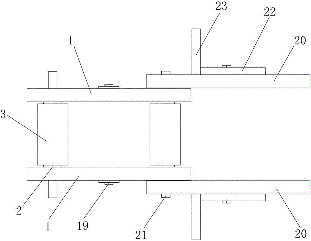
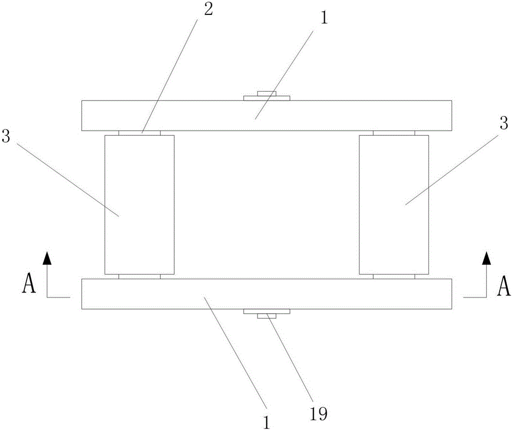
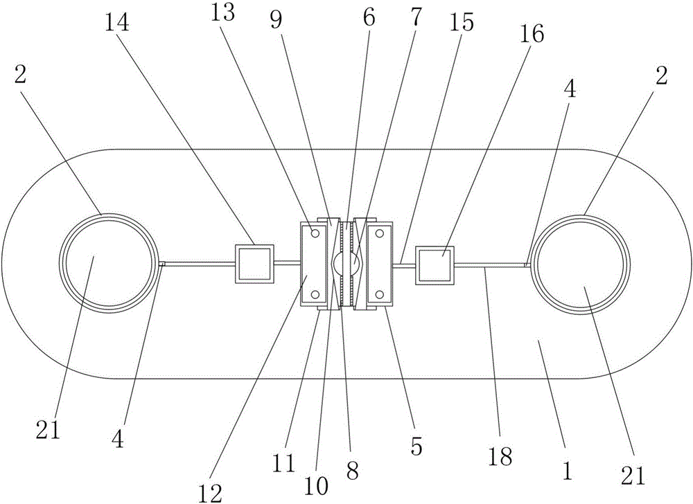
[0043] Such as Figure 1-5 As shown, the conveyor chain provided by the present invention is composed of chain links in sequence; each chain link includes two inner chain plates 1, two outer chain plates 20, two rollers 3, two sleeves 2 and two Pin shaft 21;

[0044] The two inner chain plates 1 are arranged in parallel and facing each other;

[0045] The two sleeves 2 are arranged in parallel between the two inner chain plates 1, and a circle of limiting bead is provided on the outer circumference of the sleeve 2;

[0046] The two rollers 3 are sleeved on the two sleeves 2 respectively, and a limit groove is provided on the inner circumference of the rollers 3;

[0047] The said limiting protruding ring is embedded in the limiting groove, and can be rotated relatively, and the position of the roller 3 is relatively fixed by using the cooperation of the limiting protruding ring and the limiting groove, and will not interfere with the inner chain plate 1. The inside causes w...


PUM


Abstract

The invention discloses a conveying chain. The conveying chain is formed by linking all chain links in sequence; each chain link includes two inner chain plates, two outer chain plates, two rollers, two sleeves and two pin shafts; and sealing oil storage cavities and buffer oil cavities are formed in the inner chain plates for slowly releasing lubricating oil. The lubricating oil is stored in the sealing oil storage cavities of the chain, and is buffered through two buffer oil cavities for lubricating the linked places of the inner chain plates and the outer chain plates through lubricating oil conveying channels and transverse chutes, so that the waste of the lubricating oil cannot be generated, the frequent manual lubrication is not needed, and the service life of the chain is effectively prolonged.

Description

technical field [0001] The invention relates to a chain, especially a conveying chain. Background technique [0002] At present, in the use of the chain, because the chain will be worn, it is often necessary to lubricate the chain, but the lubrication in the prior art is manual lubrication, which not only requires a lot of manpower and material resources, but also the manual lubrication operation is easy to cause lubricating oil. loss, waste. Contents of the invention [0003] Purpose of the invention: to provide a conveying chain capable of lubricating function, so as to overcome the inconvenience and waste caused by manual lubrication. [0004] Technical solution: The conveyor chain of the present invention is composed of chain links connected in sequence; each chain link includes two inner chain plates, two outer chain plates, two rollers, two sleeves and two pin shafts ; [0005] The two inner chain plates are arranged in parallel and facing each other; [0006] Th...

Claims


Application Information

Patent Timeline
IPC IPC(8): B65G17/38B65G45/08
CPCB65G17/38B65G45/08
Inventor 沈新星
Owner 江山永利百合实业有限公司
Why Eureka
Try Eureka