
Hook face longitudinal installation method

An installation method and curved surface technology, applied to the edge of the workpiece, metal processing equipment, manufacturing tools, etc., can solve the problems of difficulty in ensuring assembly accuracy and welding quality, hidden dangers of closing, and difficulty in assembly, so as to ensure assembly accuracy and welding quality, The effect of reducing welder quality and avoiding difficult processes

Active Publication Date: 2017-01-04
DALIAN SHIPBUILDING IND ENG
View PDF5 Cites 7 Cited by
  • Summary
  • Abstract
  • Description
  • Claims
  • Application Information

AI Technical Summary

Problems solved by technology

[0005] 1. The welding of the outer plate and the longitudinal bone is face-up welding, which has high requirements for welders, and it is difficult to guarantee the assembly accuracy and welding quality
[0006] 2. The outer plate, the floor plate and the platform plate form a cabin, and the working environment in the cabin is harsh and the efficiency is low
[0007] 3. Since there is no margin in the processing of the outer plate, the outer plate is often short due to welding shrinkage during the welding process of the longitudinal bone
[0008] However, if the outer panel is used as a tire, a lot of labor will be wasted in the manufacture of the tire frame, and the structure will be staggered, making assembly difficult. What’s more, the accuracy of the container device cannot be tested, which will bring great hidden dangers to the subsequent closure, so it cannot be used.

Method used


Image

  • Hook face longitudinal installation method
  • Hook face longitudinal installation method
  • Hook face longitudinal installation method

Examples


Embodiment Construction

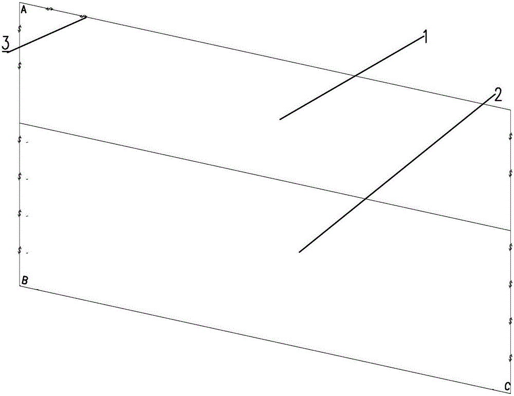
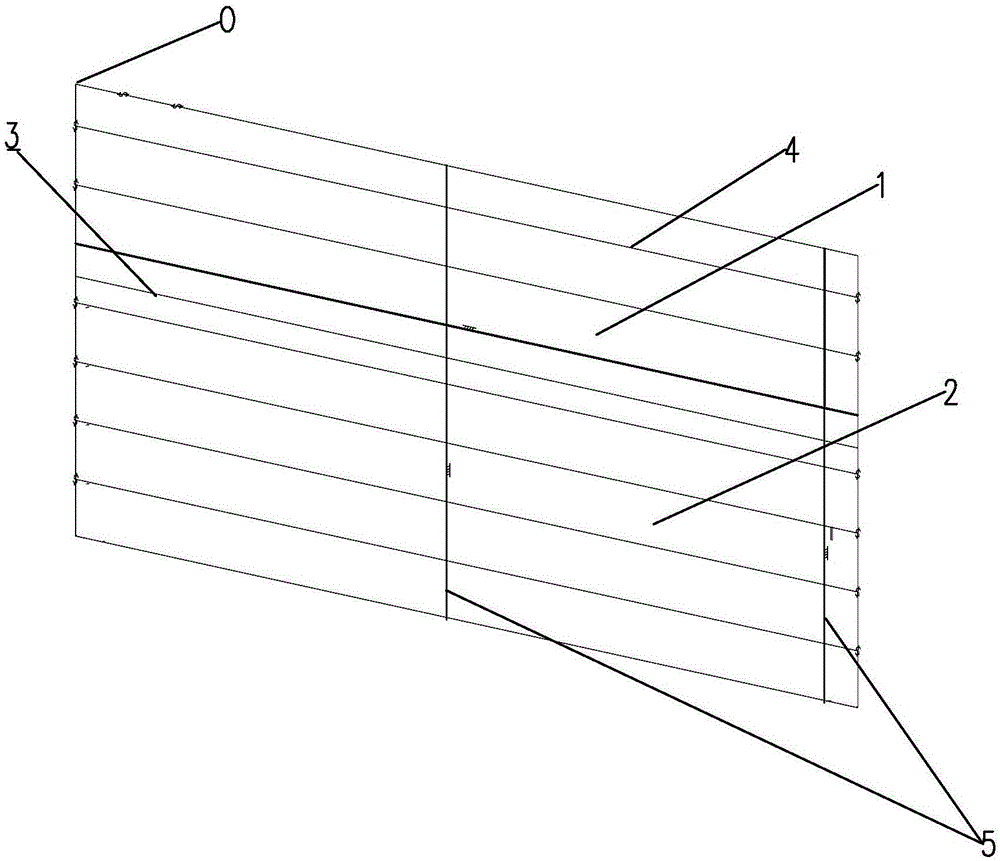
[0033] 1: Such as figure 1 with figure 2 As shown, the bulk outer panels are laid out using any free space, but the structure is facing upwards, which is convenient for marking and welding of longitudinal bones.

[0034] 2: Such as Figure 5 As shown, the suture line 3 of the first strake on the top of the figure is the scribe line 0:8 and the longitudinal line (including the platform line, the longitudinal bone line, and the suture of the lower orifice of the single strake) is drawn, and the scribe value is the rib position Data expansion value, the rib position draws longitudinal points from the top to the bottom. The relevant points fall on the rib position line 7. The lower plate mouth value 13 of the plate is recorded for future analysis. Connecting the longitudinal points of each rib position line 7 together requires a longitudinal correlation line. Note that the uppermost plate seam edge is if there is any The plate mouth value 13 left by the previous plate is added sepa...


PUM


Abstract

The invention discloses a hook face longitudinal installation method. The method includes the steps that firstly, shell plates (11) are sequentially laid, and structural faces used for connection are upward; secondly, a longitudinal line is drawn with the vertex of the first column of shell plates as the null point; thirdly, lineation is conducted on all columns of plates in the same mode in the second step, and then an overall lower plate opening value (13) is determined; fourthly, the vertex of the lower end of the lowest shell plate (11) serves as a lineation zero point, and the second step and the third step are repeated from bottom to top so as to verify accuracy of rib numbers; fifthly, longitudinals (12) are nailed on the shell plates according to the longitudinal lines, a longitudinal dip angle is formed between each shell plate and the corresponding longitudinal on each longitudinal installation line (4), and the angles need to be consistent with longitudinal through hole angles (14); sixthly, a grillage obtained in the fifth step is turned over and welded to a middle assembly structure, and flatness of the shell plates is ensured. The method guarantees assembly precision and welding quality, prevents the situation that shell plates are always short due to welding shrinkage in the longitudinal welding process, reduces cost loss, guarantees health of staff, and improves overall efficiency.

Description

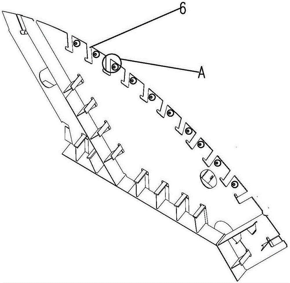
Technical field [0001] The invention relates to the field of ship manufacturing technology, and more specifically, to a process for installing the longitudinal frame of the outer plate of the bilge part of the ship. Background technique [0002] As the world shipping market continues to slump, competition in the shipbuilding market has become more intense. Improving work efficiency, reducing welders' construction difficulty, reducing welders' technical level, controlling steel plate accuracy errors, improving labor, site, environment, and efficiency, and reducing shipbuilding costs are a major focus of ship construction work. [0003] Due to the structural characteristics of container ships, the cargo hold is in a stepped shape, such as Picture 11 As shown, the outer plate 11 has a large linear curvature, a wide distribution area, and a large angle change of the longitudinal bones 12. The conventional construction of the block is the inverted method with the platform as the tire t...

Claims


Application Information

Patent Timeline
IPC IPC(8): B23K33/00
CPCB23K33/00
Inventor 孙洪国徐大宝石志东单忠伟张学东
Owner DALIAN SHIPBUILDING IND ENG
Learn More