
Laser impact riveting mold, riveting system and laser impact riveting method for sheet metal

A laser shock, sheet metal technology, applied in laser welding equipment, forming tools, manufacturing tools, etc., can solve the problems of small lateral impact force, small embedded amount, low connection strength, etc., to increase the degree of path change, increase the clip Corner, effect of shortening path length

Active Publication Date: 2017-10-17
SHANDONG UNIV
View PDF9 Cites 0 Cited by
  • Summary
  • Abstract
  • Description
  • Claims
  • Application Information

AI Technical Summary

Problems solved by technology

Obviously, a smaller lateral impact force will inevitably lead to a smaller bottom size, and a smaller size difference between the mouth and the bottom, and eventually lead to a small amount of embedding, insufficient mechanical interlock and low connection strength.
(3) Although the riveting and welding composite structure formed by the synchronous riveting and welding method can greatly improve the connection strength of the plates, this method requires the plates to have a very clean surface, otherwise it is difficult to weld through high-speed impact

Method used


Image

  • Laser impact riveting mold, riveting system and laser impact riveting method for sheet metal
  • Laser impact riveting mold, riveting system and laser impact riveting method for sheet metal
  • Laser impact riveting mold, riveting system and laser impact riveting method for sheet metal

Examples


Embodiment 1

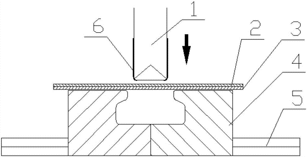
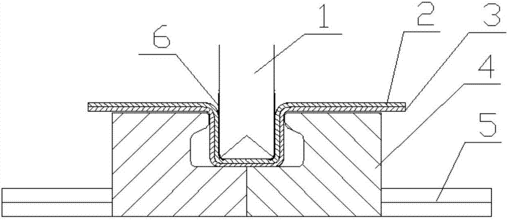
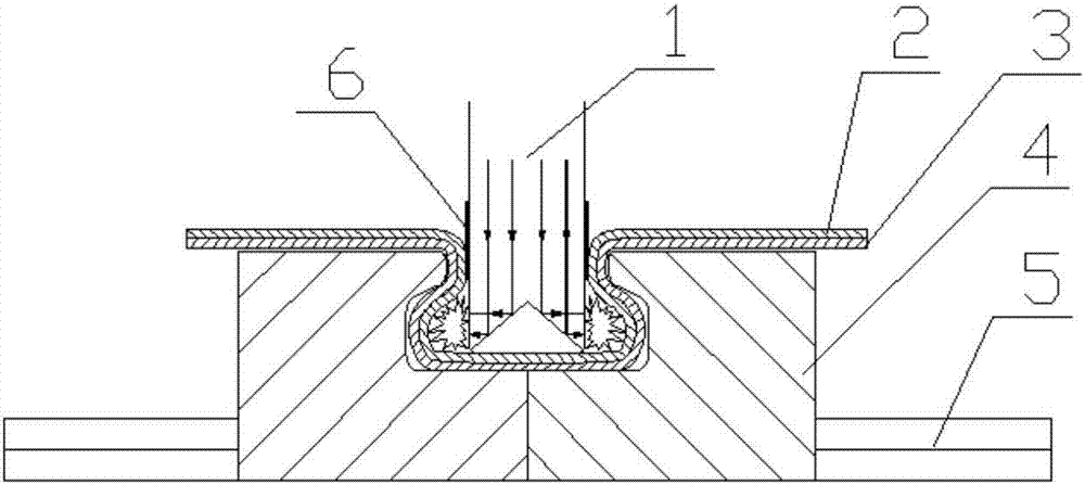
[0080] Such as Figure 1 to Figure 4 As shown, a laser impact riveting die for a plate comprises an upper die 1 and a lower die 4, the upper die 1 is a convex die, the lower surface of the upper die 1 forms a lower pressing surface for the plate, and the material of the upper die 1 is Transparent; the lower end side of the upper mold 1 is covered with an energy absorbing layer 6, and the material in the energy absorbing layer 6 is ionized to form plasma when the laser is irradiated; the lower mold 4 is a concave mold, and grooves are arranged on the concave mold. The inner width of the groove is larger than the width of the opening at the upper end, and the groove is assembled by two parts arranged oppositely;

[0081] The width of the pressing surface of the upper die 1 is smaller than the width of the upper opening of the groove.

[0082] The upper mold 4 has a quadrangular prism structure, and a laser beam path changing structure is arranged inside the upper mold 4 , which...

Embodiment 2

[0085] The difference from Embodiment 1 is that the laser beam path changing structure is a refractive index changing section, and the refractive index of the material in the refractive index changing section changes abruptly, along the direction of laser transmission, the direction of the laser beam is changed by changing the refractive index of the material . The material of the laser propagation path upstream of the interface is the same material, which is referred to as the first material here for convenience of description; the material of the laser propagation path downstream of the interface is the same material, and similarly, for the convenience of description, it is referred to as the first material here. for the second material. The interface between the first material and the second material, that is, the refraction surface is a quadrangular pyramid, the four sides of the bottom surface of the quadrangular pyramid coincide with the four sides of the upper mold resp...

Embodiment 3

[0087] The difference from Embodiment 1 is that the upper mold 1 is a cylindrical structure, and the refractive surface of the refractive index changing section encloses a conical structure, and the apex of the cone is set toward the first material.


PUM

PropertyMeasurementUnit
thicknessaaaaaaaaaa

Abstract

The invention discloses a plate laser impact riveting die, a riveting system and a laser impact riveting method. The material of the mold is transparent; the lower surface or / and lower side of the upper mold is covered with an energy absorbing layer, or an energy absorbing layer is coated on the upper surface of the plate to be riveted. , ionize to form plasma; the lower mold is a die, the die is provided with a groove, the inner width of the groove is greater than the width of the opening at the upper end, and the groove is assembled from two opposite parts; The width of the pressing surface of the upper mold is smaller than the width of the opening of the upper end of the groove. It has the advantages of large riveting depth, large amount of interlocking embedding of riveting buttons, no special treatment on the surface of the plate, and is very suitable for multi-pulse laser impact riveting.

Description

technical field [0001] The invention belongs to the field of advanced laser manufacturing, and in particular relates to a plate laser impact riveting mold, a riveting system and a laser impact riveting method. Background technique [0002] With the rapid development of industries such as automobiles and airplanes, the requirements for sheet metal connection technology are getting higher and higher, and a variety of rivetless connection technologies have emerged as the times require. Chinese patent document 200810014018.1 first proposed a pulse laser micro-riveting method for ultra-thin plates and its special device. This method uses the explosive plasma shock wave induced by the pulsed laser beam to separate the upper plate with a thickness of less than 0.1mm and the lower plate with holes. riveted together. Since the pre-set holes in the lower plate will affect the sealing performance of the connectors, and at the same time, in order to further improve the connection stren...

Claims


Application Information

Patent Timeline
Patent Type & Authority Patents(China)
IPC IPC(8): B23K26/356B21D37/10B21D39/02
CPCB21D37/10B21D39/026B23K26/356
Inventor 季忠王建峰刘韧郑超梁萌
Owner SHANDONG UNIV
Learn More