A double-disc rotary compact energy reducer and its application method

A compact energy reducer technology, which is applied in radiation therapy, X-ray/γ-ray/particle irradiation therapy, treatment, etc., can solve the problems of high mechanical positioning requirements and huge devices, and achieve small size and reduced number , the effect of reducing the number of object blocks

Active Publication Date: 2018-12-28
CHINA INSTITUTE OF ATOMIC ENERGY
View PDF5 Cites 0 Cited by
  • Summary
  • Abstract
  • Description
  • Claims
  • Application Information

AI Technical Summary

Problems solved by technology

For different energies, objects of different thicknesses need to be corresponded to. Therefore, the mechanical positioning requirements for the position of the objects are also relatively high, and the whole device is relatively large.

Method used


Image

  • A double-disc rotary compact energy reducer and its application method
  • A double-disc rotary compact energy reducer and its application method
  • A double-disc rotary compact energy reducer and its application method

Examples


Embodiment Construction

[0013] The present invention will be described in detail below with reference to the drawings and embodiments.

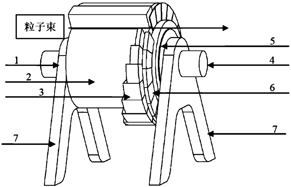
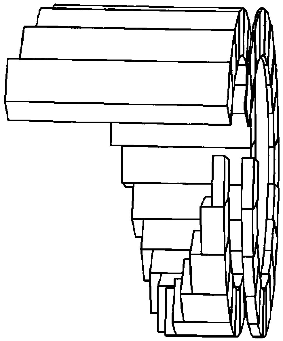
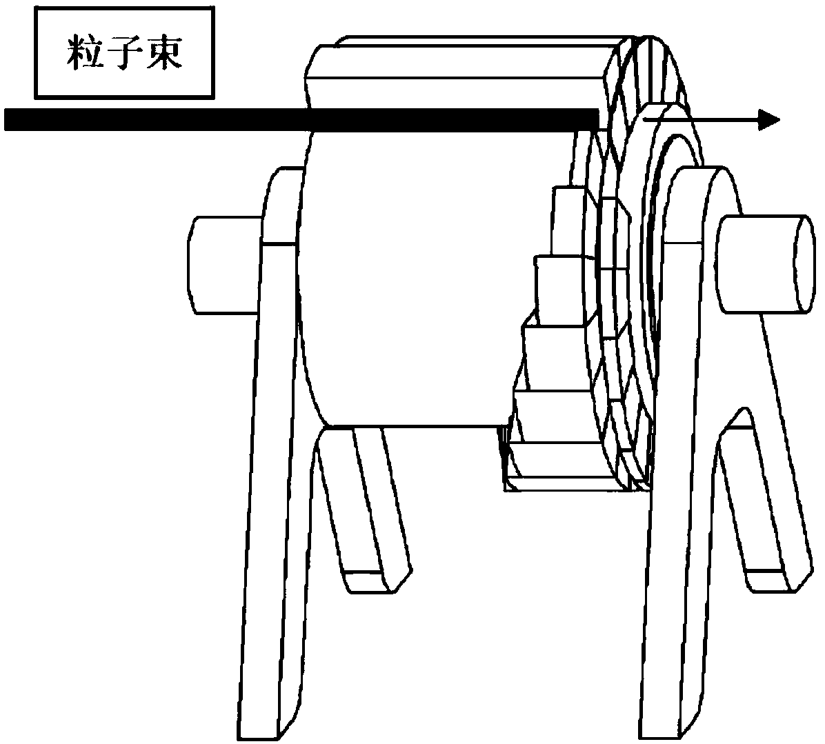
[0014] Such as figure 1 As shown, the present invention provides a dual-disk rotating compact deenergizer for changing the energy of a particle beam drawn by an accelerator, including: a first rotating electric machine 1, a first rotating support disk 2, and a first group of object blocks 3 , A second rotating electric machine 4, a second rotating support plate 5, a second group of object blocks 6, and a degrader support device 7. The first group of object blocks is installed on the first rotating support plate, the first rotating motor is connected to and drives the rotation of the first rotating support plate; the second group of object blocks is installed on the second rotating support plate, the second rotating The motor is connected to and drives the rotation of the second rotating support plate. The first and second rotating support disks are both installed on ...


PUM


Abstract

The invention relates to a double-plate rotary type compact degrader and a use method thereof. The degrader comprises a pair of compact double-plate spiral rotating mechanisms. The double plates are compactly and symmetrically mounted in an equal-diameter and equal-central-structure manner. Each plate is provided with a group of object blocks with different thicknesses. According to an energy refining requirement, the number of each group of object blocks can be 10-20. The number of one group of object blocks can be same with or different from that of the other group of object blocks. The two groups of object blocks abut against each other. Two sets of independent motor rotating and supporting mechanisms are utilized. Through independently rotating the two plate type mechanisms, 100-400 combinations of physical blocks with different thicknesses can be realized. Through utilizing a double-plate arrangement combination manner, the double-plate rotary type compact degrader has advantages of remarkably reducing number of object blocks, improving energy refining precision, reducing number of object blocks, correspondingly reducing sizes of the integral degrader, and supplying a small settlement solution for developing a more compact proton or heavy-ion cancer treatment device.

Description

Technical field [0001] The invention belongs to the field of particle accelerator technology and particle therapy, and specifically relates to a device for changing the energy of a particle beam drawn from an accelerator. Background technique [0002] In the field of particle accelerators, especially in the field of accelerator technology for proton and heavy ion therapy, in order to reduce the cost of equipment, most of the compact fixed energy accelerators are used as the particle source. In order to change the energy of the particle beam derived from the accelerator, the particle beam The different irradiation depths of the lesions in the human body are usually realized by using a degrader device. Such as Figure 5 As shown, a set of proton therapy system consists of four parts: 1 cyclotron, 2 deenergizer, 3 beam lines, 4 rotating gantry treatment head. Particle beams usually use object block blocking methods to change the energy. At present, a commonly used energy degrader te...

Claims


Application Information

Patent Timeline
Patent Type & Authority Patents(China)
IPC IPC(8): A61N5/10
CPCA61N5/1042A61N2005/1087A61N2005/1095
Inventor 管锋平魏素敏王飞
Owner CHINA INSTITUTE OF ATOMIC ENERGY
Why Eureka
Try Eureka