
Movable retractable device and movable retractable solar panels

A technology of solar panels, moving and stretching, applied in mobile/directional solar collectors, solar thermal power generation, solar thermal energy, etc., can solve the problems of low utilization rate and inability to fully utilize sunlight, and achieve small space utilization and structural Simple, Widely Applicable Effects

Inactive Publication Date: 2018-03-20
UNIV OF SHANGHAI FOR SCI & TECH
View PDF5 Cites 1 Cited by
  • Summary
  • Abstract
  • Description
  • Claims
  • Application Information

AI Technical Summary

Problems solved by technology

However, in traditional methods, solar panels are usually fixedly installed in these places and cannot be moved. Since the angle of sunlight is constantly changing throughout the day, the fixedly installed panels cannot fully utilize the sunlight, and the utilization rate is very high. Low

Method used


Image

  • Movable retractable device and movable retractable solar panels
  • Movable retractable device and movable retractable solar panels
  • Movable retractable device and movable retractable solar panels

Examples


Embodiment Construction

[0022] In order to make the technical means, creative features, goals and effects of the present invention easy to understand, the following embodiments will specifically illustrate the movable retractable device and the movable retractable solar panel of the present invention in conjunction with the accompanying drawings.

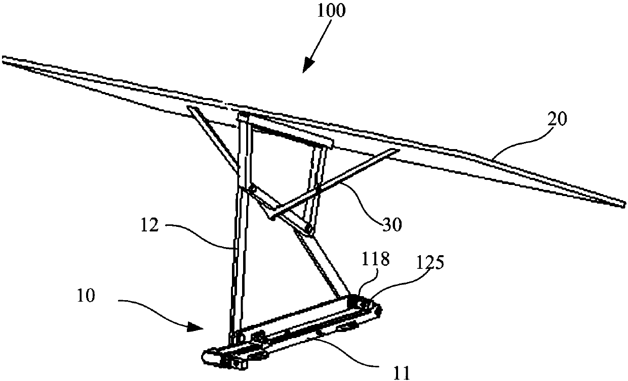
[0023] figure 1 It is a schematic structural diagram of a movable shrinkable solar cell panel in an embodiment of the present invention.

[0024] Such as figure 1 As shown, in this embodiment, the movable and shrinkable solar panel 100 is installed on the roof of the car to fully contact with the sunlight and fully utilize the solar energy to generate electricity.

[0025] The movable and retractable solar panel 100 includes a movable telescopic device 10 , a solar panel 20 and a supporting frame 30 .

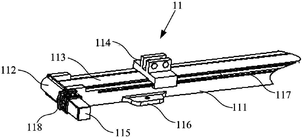
[0026] The movable telescopic device 10 is connected with the vehicle roof by bolts, and it includes a translation part 11 and a telescopic part 12 .

...


PUM


Abstract

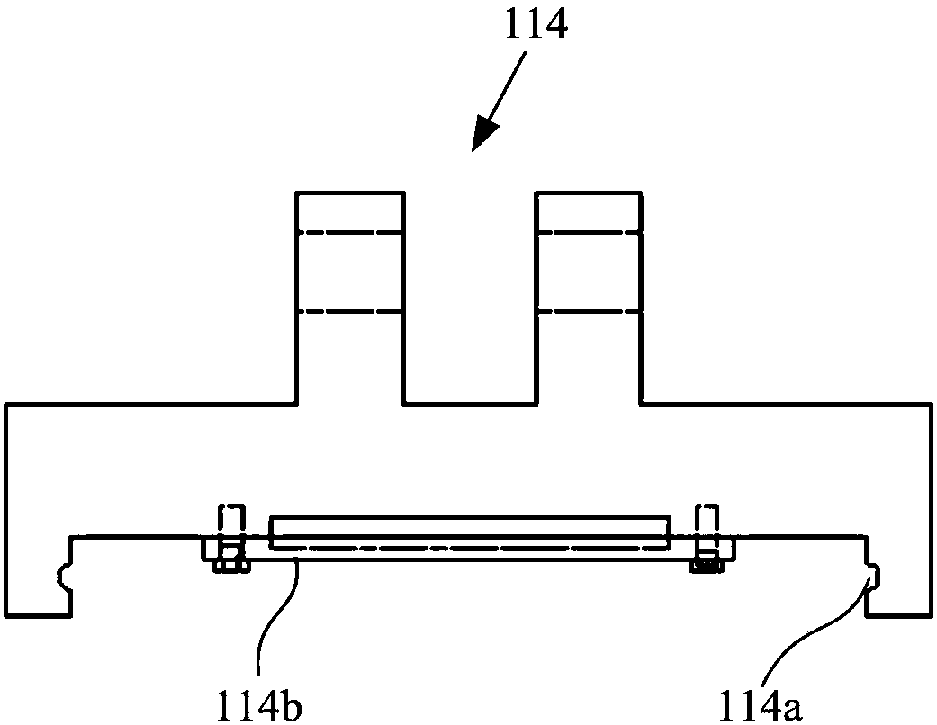
The invention provides a movable telescopic device, which is characterized in that it has: a translation part, including a fixed slide rail, two rollers respectively arranged at both ends of the slide rail, a transmission belt set on the two rollers, a The slider on the top and the first motor that drives the drum to rotate; and the telescopic part, including a fixed rod fixedly connected to the slider, an active rod connected to one end of the fixed rod in rotation, and a driven rod connected to the other end of the fixed rod in rotation Rod, a connecting rod unit that is rotatably connected with the driving rod and the driven rod, and a second motor that is fixed on the side of the fixed rod and is rotatably connected with the driving rod, wherein the first motor drives the roller to rotate and drives the transmission belt to drive the slider to Moving on the transmission belt, the second motor drives the active rod to swing and drives the connecting rod unit to stretch and swing. The present invention also provides a solar cell panel with a movable telescopic device, which can move horizontally while being telescopic, and can make full use of solar energy.

Description

technical field [0001] The invention relates to the technical field of solar battery panels, in particular to a movable and telescopic solar battery panel. Background technique [0002] With the continuous development of the economy and the continuous progress of science and technology, more and more attention has been paid to solar energy. As a clean new energy, solar energy has been widely used in various fields. Solar panels can directly or indirectly convert solar energy into electrical energy. At present, solar panels are mostly used in solar water heaters, solar street lights, and there are many places where solar energy is used in life, such as balconies, doors and windows, cars, etc. However, in traditional methods, solar panels are usually fixedly installed in these places and cannot be moved. Since the angle of sunlight is constantly changing throughout the day, the fixedly installed panels cannot fully utilize the sunlight, and the utilization rate is very high. ...

Claims


Application Information

Patent Timeline
Patent Type & Authority Patents(China)
IPC IPC(8): H02S20/30F24S30/20F24S30/455
CPCF24S25/10G05D3/105H02S20/30H02S30/20Y02E10/47Y02E10/50
Inventor 宫赤坤张吉祥刘鹏程赵超凡吉喆匡毅王旭
Owner UNIV OF SHANGHAI FOR SCI & TECH
Learn More