RGB adjustable color luminescence apparatus driving system and method

A technology of light emitting device and driving system, which is applied in the direction of instruments, static indicators, etc.

Inactive Publication Date: 2016-12-21
SHANGHAI ZHANHUISHI IND CO LTD
View PDF5 Cites 2 Cited by
  • Summary
  • Abstract
  • Description
  • Claims
  • Application Information

AI Technical Summary

Problems solved by technology

[0003] The present invention provides an RGB adjustable color light-emitting device driving system and method to solve the defects caused by the prior art

Method used


Image

  • RGB adjustable color luminescence apparatus driving system and method

Examples


Embodiment Construction

[0027] In order to make the technical means, creative features, objectives and effects of the invention easy to understand, the present invention will be further elaborated below in conjunction with specific diagrams.

[0028] A preferred embodiment of the present invention provides a driving system and method for an RGB adjustable color light emitting device. The purpose is to simplify the operation process of the light emitting device, adjust the brightness of the light emitting device to achieve energy saving effect, and increase the service life.

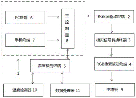
[0029] Such as figure 1 As shown, a RGB adjustable color light emitting device driving system and method, wherein the driving system includes a main control terminal 1, an RGB source driving terminal 2, an analog signal conversion terminal 3, an RGB pixel driving terminal 4, and a temperature detection terminal 5;

[0030] The main control terminal 1 includes a PC terminal 6, a mobile phone terminal 7 and a main controller 8, an...


PUM


Abstract

The invention discloses an RGB adjustable color luminescence apparatus driving system and method. The system comprises a master control terminal, an RGB source driving terminal, an analog signal conversion terminal, an RGB pixel driving terminal and a temperature detection terminal, wherein the master control terminal comprises a PC terminal, a mobile phone terminal and a master controller; the RGB source driving terminal is used for receiving each Z groups of RGB digital driving signals from the master controller, obtaining Z groups of RGB analog driving signals through converting the RGB digital driving signals and transmitting the RGB analog driving signals to the analog signal conversion terminal; the analog signal conversion terminal is used for receiving the Z groups of RGB analog driving signals from the RGB source driving terminal, converting the Z groups of RGB analog driving signals into Z groups of analog driving signals comprising R, G, B and W four-color pixel driving voltages, and outputting the analog driving signals to the RGB pixel driving terminal; the RGB pixel driving terminal is used for converting the received Z groups of analog driving signals comprising the R, G, B and W four-color pixel driving voltages into electric signals and outputting the electric signals to a circuit board; and the circuit board controls a display area of a luminescence apparatus to work.

Description

technical field [0001] The invention relates to the technical field of driving a light emitting device, in particular to a driving system and method for an RGB adjustable color light emitting device. Background technique [0002] As a kind of light-emitting device, LED light-emitting device has been widely used outdoors. You can see some billboards as LED light-emitting devices everywhere. There will be better development of light-emitting devices in the future, but the current ordinary LED light-emitting device system is inconvenient to operate. Moreover, the light-emitting device has the disadvantages of low contrast, low luminous efficiency, short service life and single color. Contents of the invention [0003] The invention provides an RGB adjustable color light emitting device driving system and method to solve the defects caused by the prior art. [0004] To achieve the above object, the present invention provides the following technical solutions: a RGB adjustable...

Claims


Application Information

Patent Timeline
Patent Type & Authority Applications(China)
IPC IPC(8): G09G3/20
CPCG09G3/2003
Inventor 马发国张祖年
Owner SHANGHAI ZHANHUISHI IND CO LTD
Why Eureka
Try Eureka