A Distributed Nonlinear Driving Deployment Method for Large Aperture Annular Reflectors

A circular reflector and non-linear technology, applied in antennas, instruments, design optimization/simulation, etc., can solve problems such as long force transmission path, large deployment force, and large energy loss, so as to reduce antenna deployment force and meet space requirements Dimensional constraints, the effect of improving the reliability of unfolding

Active Publication Date: 2019-02-19
XIAN INSTITUE OF SPACE RADIO TECH
View PDF5 Cites 0 Cited by
  • Summary
  • Abstract
  • Description
  • Claims
  • Application Information

AI Technical Summary

Problems solved by technology

[0005] At the same time, from the perspective of energy utilization of the entire system, the input energy utilization rate of the current deployment scheme is low
Among them, in the spring driving stage, the initial output torque of the linear vortex spring is large, and at this time the mesh surface is loose and no unit is locked, the input energy required by the system is small, and most of the energy input by the vortex spring is wasted; stage, when the remote unit is deployed at the end of the deployment, the mesh surface is tensed, and concentrated input energy is required. At this time, the power transmission path of the motor through the power rope is long, and the friction causes the tension transmitted to the remote driving rope to be greatly reduced. The required deployment force is too large and the energy loss is large

Method used


Image

  • A Distributed Nonlinear Driving Deployment Method for Large Aperture Annular Reflectors
  • A Distributed Nonlinear Driving Deployment Method for Large Aperture Annular Reflectors
  • A Distributed Nonlinear Driving Deployment Method for Large Aperture Annular Reflectors

Examples


Embodiment

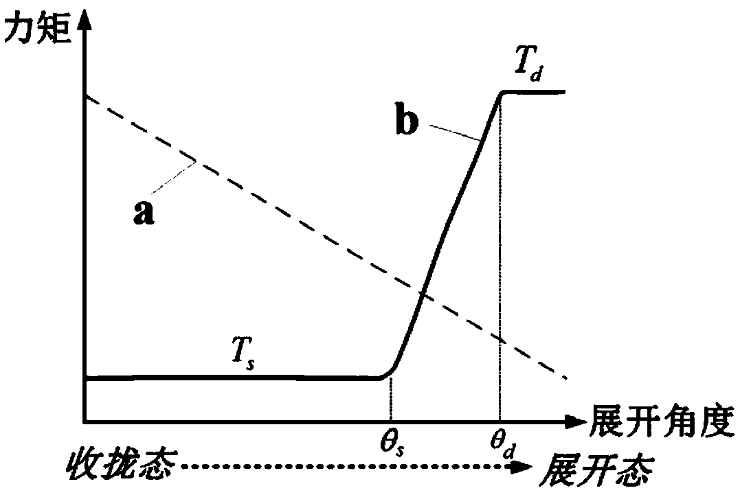
[0059] Take the Astromesh loop antenna with 30 units and 16m expansion aperture as an example. Assume that the initial moment corresponding to the linear vortex spring used in the hinge is 4Nm, and the moment after unfolding is 2Nm. Figure 4 Among them, I is the change curve of the hinge driving torque with the expansion angle, II and III are the output torque characteristics of the distal and proximal nonlinear springs determined by formulas (4) and (5), respectively.

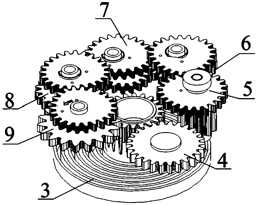
[0060] According to the method in "A Passive Deployment Driver for Spatial Mesh Antenna Based on Noncircular Gears", a conversion device using four-stage noncircular gear meshing can be designed to realize the conversion of the existing linear torsion spring force.

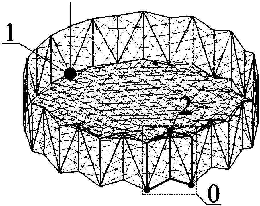
[0061] Figure 5 is the unit number and the distribution of the driving force of the proximal and distal hinges, c is the installation position of the motor, and the driving torque curve of the hinges of units 7 to 22 in area d is Figure 4 In ...


PUM


Abstract

The invention relates to a distributed nonlinear drive deployment method for a large-diameter annular reflector. The distributed nonlinear drive deployment method comprises the following steps of: (1), obtaining the nonlinear output torque of a hinge of an annular reflector by calculation, and obtaining the output torque Tfar of a far-end hinge and the output torque Tnear of a near-end hinge; (2), obtaining the corresponding relationship of the rotational angle of a driving gear at the far-end hinge and the rotational angle of a driven gear at the far-end hinge shown in the specification, and the corresponding relationship of the rotational angle of a driving gear at the near-end hinge and the rotational angle of a driven gear at the near-end hinge shown in the specification by calculation; (3), calculating a transmission ratio of the driven gear to the driving gear at the far-end hinge and a transmission ratio of the driven gear to the driving gear at the near-end hinge at any time; and (4), respectively obtaining corresponding gear trains by calculation according to the transmission ratio ifar and the transmission ratio inear. By means of the distributed nonlinear drive deployment method disclosed by the invention, energy distribution of a system in a deployment process is optimized; furthermore, the motor output energy in the deployment process is reduced; and thus, the deployment driving force is reduced.

Description

technical field [0001] The invention relates to a method for deploying an annular reflector, in particular to a method for deploying a large-aperture annular reflector with distributed nonlinear drive. Background technique [0002] In recent years, the new generation of mobile communication satellites, electronic reconnaissance satellites, and data relay satellites have put forward an urgent need for large-aperture mesh expandable antenna reflectors in order to detect low-power signals. Among various mesh antenna schemes, the ring truss-type deployable antenna has become the current large-scale spaceborne deployable antenna due to its simple structure, high reliability, large deployment ratio, light weight, and easy realization of large-diameter reflectors. The most ideal structural form. A typical ring-shaped truss-type deployable antenna is the Astromesh configuration proposed by Northrop Grumman Company of the United States, which consists of a mesh system and a surround...

Claims


Application Information

Patent Timeline
Patent Type & Authority Patents(China)
IPC IPC(8): G06F17/50H01Q15/20
CPCG06F30/20G06F2111/04H01Q15/20
Inventor 杨军刚肖勇赵治华王超琦冯涛李洋张欣
Owner XIAN INSTITUE OF SPACE RADIO TECH
Why Eureka
Try Eureka