
A Spinning Method for Revolving Curved Surface Parts with Front and Back Mounting Edges

A technology of rotating curved surface and parts, which is applied in the field of spinning and machining of rotating curved surface parts. It can solve the problems of unstable spinning elongation, inner sleeve spinning cracks, and large surface contour, so as to solve the problem of fracture, Effect of reducing extension resistance and improving surface quality

Active Publication Date: 2018-08-03
AECC AVIATION POWER CO LTD
View PDF7 Cites 0 Cited by
  • Summary
  • Abstract
  • Description
  • Claims
  • Application Information

AI Technical Summary

Problems solved by technology

[0010] The purpose of the present invention is to propose a method for spinning curved surface parts with front and rear mounting edges, which solves the problems of inner sleeve spinning cracks, large profile and unstable spinning elongation, and realizes the processing requirements of components

Method used

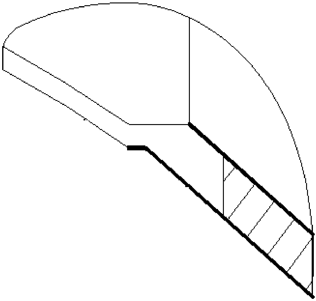
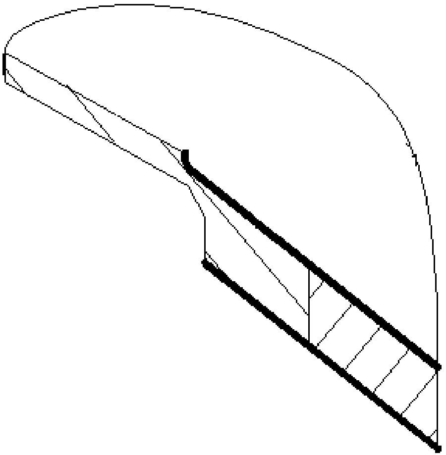

Image

  • A Spinning Method for Revolving Curved Surface Parts with Front and Back Mounting Edges
  • A Spinning Method for Revolving Curved Surface Parts with Front and Back Mounting Edges
  • A Spinning Method for Revolving Curved Surface Parts with Front and Back Mounting Edges

Examples


Embodiment Construction

[0058] Below in conjunction with accompanying drawing and specific embodiment the present invention is described in further detail:

[0059]The specific steps of the spinning method of the rotary curved surface part with the front and rear mounting sides of the present invention are as follows:

[0060] First turn the forging to the pronation size, then spin the middle section, and then finish the non-spinning section.

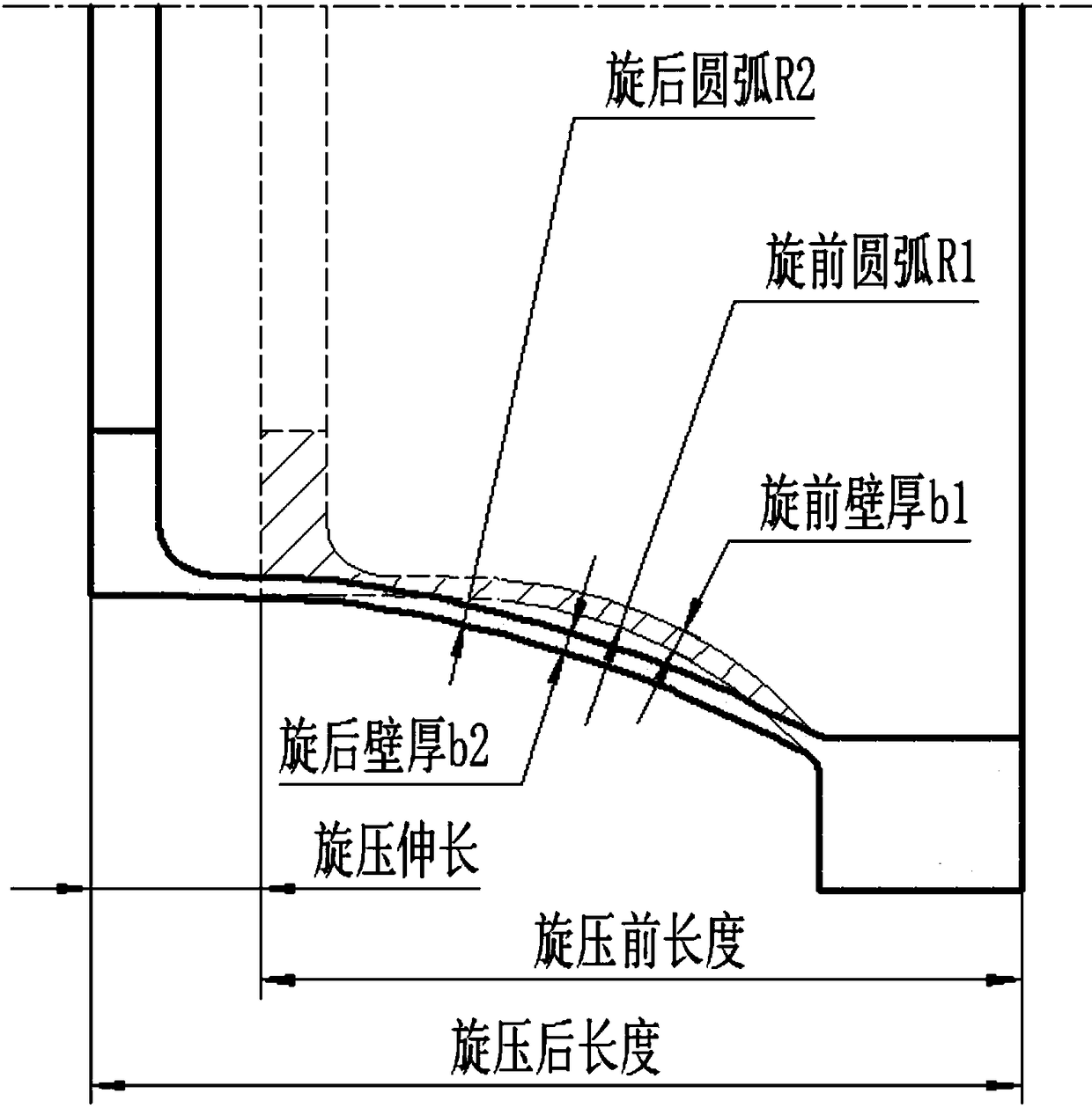
[0061] Part spinning is a type of thinning spinning. According to the law of volume invariance, in order to ensure the shape and size of the parts after spinning, it is necessary to find out the changes in wall thickness reduction and shape, diameter and length of the spinning section, and then determine the shape and size of the blank before spinning.

[0062] like image 3 As shown, wall thickness reduction and spinning elongation.

[0063] Knowing the length of supination, thickness of the wall of supination, and radius of the arc of supination, and the ...


PUM


Abstract

The invention discloses a rotary pressing method of a rotation curve part with front and back mounting sides. The method comprises the steps that firstly, a forge part is turned into the size before rotation; secondly, a middle segment is rotatably pressed, the large end back face of the part is turned into a step face, meanwhile, a step on the end face of a mould is removed, the back face of a large mounting side is attached to the end face of the mould, the axis of the part and the axis of the mould are kept parallel, and the edge of the outer circle of the small end of the part is chamfered; thirdly, the rotary pressing face serves as the turning standard, the non-rotary-pressing segment is subject to finish turning machining, through control over the thickness reduction of the wall thickness, the rotary pressing elongation amount is stabilized, through the theoretical analysis and the rotary pressing test, the shape face structure and the positioning compressing manner of the rotary pressing mould are determined, the rotary pressing elongation is changed in the required direction, and therefore the shape face distortion is prevented, the traditional thought that part machining depends on large and small end positioning is broken through, the new thought that the curve serves as the machining standard is created, and coordinating and unifying between the rotary pressing shape face and the machining surface are achieved.

Description

【Technical field】 [0001] The invention belongs to the field of aviation manufacturing and belongs to the category of mechanical processing, and relates to a spinning method of a rotary curved surface part with front and rear mounting edges. 【Background technique】 [0002] The main part of the inner casing of the aero-engine combustor casing is welded by electron beams in the front and rear sections, and the blanks of the two sections are GH141 forgings. The design requires that the middle part of the front section of the inner sleeve be strengthened by spinning to improve the strength, hardness and fatigue resistance. [0003] Due to the special structure of the part and the unevenness of the spinning deformation, the spinning deformation of the front section of the inner sleeve is very large, which causes the deformation of the non-spinning section to be also large. Due to the lack of experience in forging blank spinning and the technical data that can be used for referenc...

Claims


Application Information

Patent Timeline
Patent Type & Authority Patents(China)
IPC IPC(8): B21D22/16
CPCB21D22/16
Inventor 李新孝党文哲毛克亮高瑛黄应军张军强燕全社
Owner AECC AVIATION POWER CO LTD
Learn More